Instructions – Reznor UEAS Unit Installation Manual User Manual
Page 9
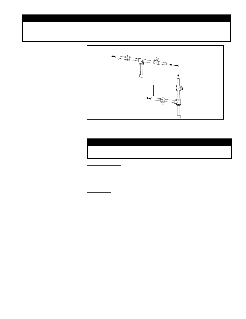
FIGURE 5 - Gas
connection is at the
pipe nipple that extends
outside the cabinet
Illustration shows
both a vertical and
horizontal gas supply;
requirements are the
same.
From Gas Supply
(horizontal or vertical)
Manual shutoff
Pipe nipple extending
outside the cabinet.
Drip
Leg
To Gas Valve
(inside the
cabinet)
To Gas Valve
(inside the
cabinet)
Ground
Joint
Union
Drip
Leg
Ground
Joint Union
Manual shutoff
WARNING
All components of a gas supply system must be leak tested prior to placing
equipment in service. NEVER TEST FOR LEAKS WITH AN OPEN FLAME. Failure to
comply could result in personal injury, property damage or death.
7.1.3 Valve Outlet or
Orifice Pressure Setting
Measuring valve outlet gas pressure cannot be done until the heater is in opera-
tion. It is included in the steps of the “Check-Test-Start” procedure in Paragraph
11. The following warnings and instructions apply.
WARNING
Valve outlet gas pressure must never exceed 3.5” w.c.
for natural gas and 10” w.c. for propane gas.
For Natural Gas: When the heater leaves the factory, the combination
gas valve is set so that the valve outlet gas pressure for a single-stage
valve is regulated to 3.5” w.c. Inlet supply pressure to the valve for natural
gas must be a minimum of 5” w.c. or as noted on the rating plate and a
maximum of 14” w.c.
For Propane: The heater is shipped factory equipped for use with natural gas. A
propane conversion kit is included. Follow the instructions in Paragraph 7.1.4 to
convert for use with propane.
At startup, measure the valve outlet pressure. Refer to the pressure chart on page
10 for correct outlet pressure.
When using propane, the inlet supply pressure to the valve must be a minimum of
11” w.c. and a maximum of 14” w.c.
Before attempting to measure or adjust valve outlet gas pressure, the inlet supply
pressure must be within the specified range both when the heater is in operation
and on standby. Incorrect inlet pressure could cause excessive valve outlet gas
pressure immediately or at some future time. If natural gas supply pressure is too
high, install a regulator in the supply line before it reaches the heater. If natural gas
supply pressure is too low, contact your gas supplier.
NOTE: A gas conversion kit for
changing from natural gas to
propane is included with each
heater. See Paragraph 7.1.4 for
conversion instructions.
Check Valve Outlet
Pressure (can only be
done after heater is
operating)
NOTE: If operating at high
altitude, outlet pressure requires
adjustment. Follow instructions
below.
Instructions
1) Locate the 1/8” output pressure tap on the valve (See FIGURE 6, page 10).
With the manual valve turned off to prevent flow to the gas valve, connect
a manometer to the 1/8” pipe outlet pressure tap in the valve.
NOTE: A
manometer (fluid-filled gauge) is recommended rather than a spring type
gauge due to the difficulty of maintaining calibration of a spring type gauge.
2) Open the manual valve and operate the heater. Depress and hold the door
safety switch. Cycle the burner once or twice to properly seat the adjustment
spring in the valve. Measure the outlet pressure of the gas valve.
Form I-UEAS, P/N 221232 R13, Page 9