2 24v control wiring connections, Rear view model ueas – Reznor UEAS Unit Installation Manual User Manual
Page 27
CAUTION: If any of the original wire as supplied with the appliance must be replaced, it
must be replaced with wiring material having a temperature rating of at least 105°C, except
for limit control, vent temperature limit, and sensor lead wires which must be 150°C. See
Hazard Levels, page 2.
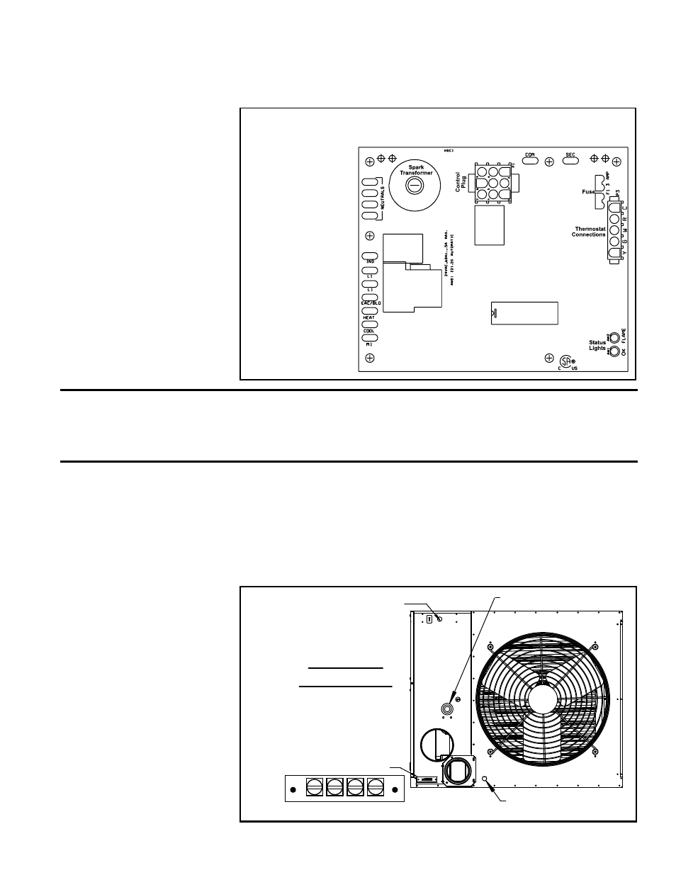
FIGURE 23 - Supply Wiring Connections at the Circuit Board
(DSI Integrated Control Module)
Supply
Wiring
Connections
1097-83-218
MODEL 1097-218
NOTE: Circuit
board is polarity
sensitive; “hot”
wire MUST BE
connected to
Terminal L1.
The terminal strip for 24 volt thermostat connection is located on the outside of the
cabinet at the back of the heater (See
FIGURE 24). Wires from the terminal strip
are factory wired to the circuit board.
Use either an optional thermostat available with the heater or a field-supplied
24-volt thermostat. Install according to the thermostat manufacturer’s instructions,
paying particular attention to the requirements regarding the location of the ther-
mostat.
8.2 24V Control Wiring
Connections
FIGURE 24 - Terminal
Strip for 24-volt Wiring
is on the Outside Rear of
the Heater
Rear View
Model UEAS
Condensate Drain
Line Voltage
Entrance
Gas Connection
Terminal Strip for
Thermostat
Connection
R G W1W2
The circuit board (See
FIGURE 23) is located inside on the bottom of the control
compartment. The circuit board is polarity sensitive. It is advisable to check the
electrical supply to be certain that the black wire is the “hot” wire and that the white
wire is the neutral wire. The supply connection made to “L1” on the circuit board
must be the “hot” wire.
Form I-UEAS, P/N 221232 R13, Page 27