Reznor UEAS Unit Installation Manual User Manual
Page 21
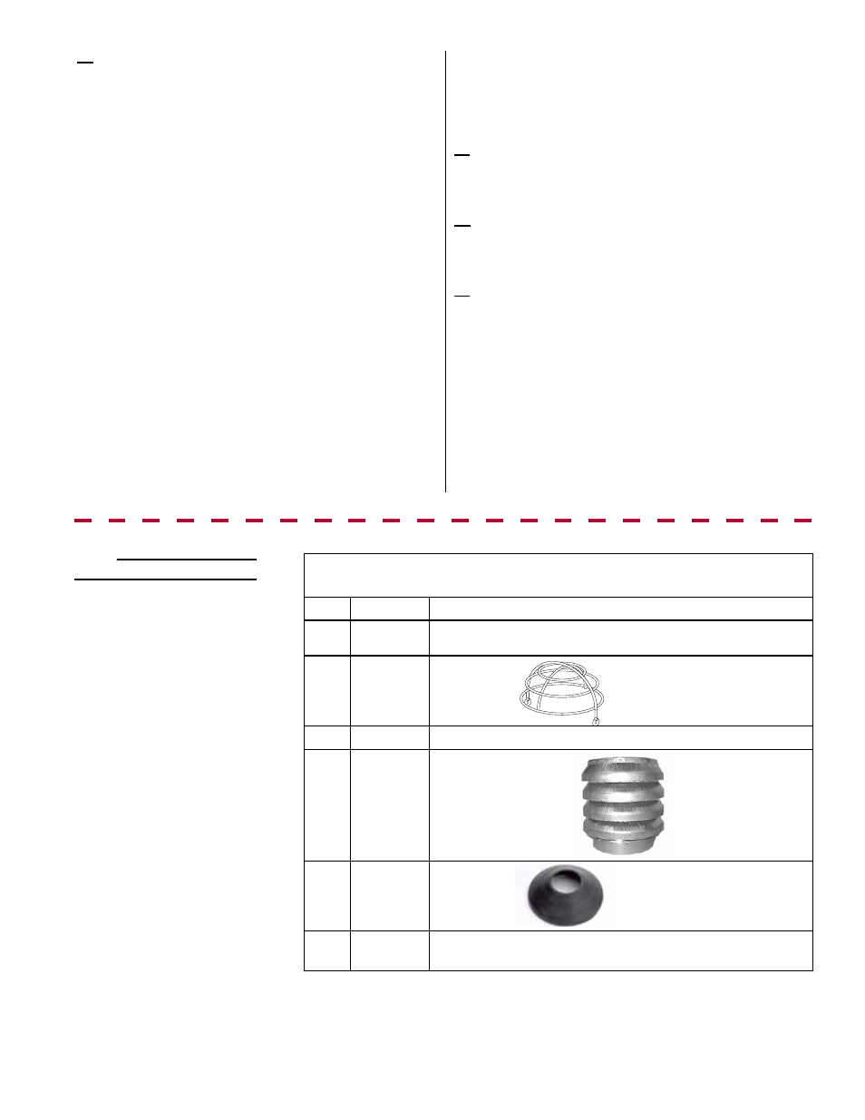
Parts in the Vertical Vent
Terminal/Combustion Air
Package (Option CC2)
Components Required - Factory and Field
7.2.3 VERTICAL VENT
TERMINAL Installation -
Option CC2
Complete Vertical Vent/Combustion Air Kit (Same as Option
CC2), P/N 221248
Qty
P/N
Description
1
221069
Concentric Adapter Box with Silicone Sealing Ring (See
Paragraph 7.2.1.9, pages 16-17.)
1
221215
Bird Guard
2
37661
Screws for Bird Guard. #10x1/2" self-drilling
1
221250
Combustion Air Inlet
1
221185
Rain Collar
1
221091
4" PVC Cap for Vent Condensate Drain Connection (See
FIGURE 8A and 9A on page 13.)
6b) Drill a hole to attach the elbow at the end and
install the pipe. Being sure the vent pipe is in the proper
flow direction, temporarily fit the elbow on the exhaust
end of the vent pipe. For easier future service, the elbow
is being attached using one field-provided 3/4” long
sheetmetal screw. Using a drill that is a size smaller than
the 3/4” long sheetmetal screw, with the elbow pointing
down, drill a pilot hole through the top center of the elbow
socket and the vent pipe.
Remove the elbow. In the elbow only, enlarge the drilled
hole to 7/32”. The elbow will be attached from the outside
in Step 8b).
With the pipe turned so that the drilled hole is at the top,
slide the end of the vent pipe out through the box and
the combustion air pipe. Position the vent pipe so that it
will extend between 3” (76mm) and 6” (152mm) past the
end of the combustion air pipe. Adjust the pipe so that
the screw hole is in the top center. Verify that the silicone
sealing ring on the box is properly seated.
Do not add
sealant to the ring.
Join the “terminal end” vent pipe to the vent pipe run.
Re-check the silicone ring to be sure that it is still
properly seated.
7. Attach the indoor portion of the combustion air
pipe. Use sheetmetal screws to attach the single-wall
combustion air pipe run to the collar on the concentric
adapter box. Seal with tape or sealant.
8. On the outside, install the inlet air guard spacers,
attach the elbow, install the bird screen, and seal or
flash around the combustion air pipe.
8a) Remove the screws holding the inlet air guard
(installed in Step 4c). Slide the spacers onto the ends of
the four spokes that support the vent pipe. Re-attach the
guard.
8b) Slide the elbow over the end of the vent pipe and
attach it with the field-provided 3/4” long sheetmetal
screw. Slide the bird screen into the socket on the open
end of the elbow. The elbow must be pointing down.
8c) Seal around the combustion air pipe with an outdoor
caulking material or a masonry cement or a combination
of flashing and caulking. Adjust the sealant and the
pipe so that the metal pipe will have a slight downward
slope to the outside. The downward slope and the 1/2”
drain hole (Step 4b) will prevent rain water from running
through the pipe into the concentric adapter box.
Installation of the horizontal vent and combustion
air system on your separated-combustion unit is
complete. Verify compliance with all venting installation
requirements, pages 12-17, and
FIGURE 16.
• Vent pipes and fittings as illustrated in
FIGURE 8A, 8B, 9A or 9B on pages 13
and 14
• Combustion air pipes (6” and 8” single-wall galvanized pipe)
• Flashing
• Sheetmetal screws, tape, primer, cement, and sealant as required
Field-supplied
requirements:
Form I-UEAS, P/N 221232 R13, Page 21