Reznor UEAS Unit Installation Manual User Manual
Page 23
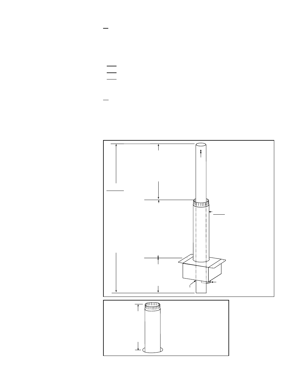
FIGURE 17 - Concentric
Adapter, Outdoor
Combustion Air Pipe,
and Concentric Vent
Pipe
Concentric
Adapter Box
X = length of combustion
air pipe required through
and above the roof. Height
from box to top of inlet
air pipe must not
exceed 48 (1219mm).
Minimum height above
the roof is 18 (457mm)
and must be higher than
anticipated snow depth.
FIRST,
1) Determine length (X) of
combustion air pipe (see
requirements on the left).
2) Attach the 8 combustion air
pipe to the collar on the box.
3) Inside, use field-supplied
hardware to attach the box
to the roof.
V
ent Flow
23 (584mm) minimum
Cold Climate NOTE:
In geographic areas where
the design ambient is -10°F
or lower, this minimum
height is 34 (864mm).
Collar for attaching
indoor 6 diameter
Combustion Air Pipe
SECOND,
Extend one
continuous
piece of
vent pipe
through the
attached box,
through the
combustion
air pipe, and
the required
height above
the combustion
air pipe.
Silicone Ring
12 (305mm) minimum -
6 (152mm) through the
box plus enough length
below to attach to coupler
Outside view with concentric
adapter box attached to
underside of roof. Install
field-supplied flashing at
roof opening.
Snow Clearance
18 (457mm)
minimum
(NOTE: Maximum
from concentric
adapter box is
48 (1219mm).
FIGURE 18 - Outside
View of Combustion Air
Pipe with Box Attached
to Under Side of Roof
6. Determine the length and install the “terminal end” vent pipe.
6a) Refer to FIGURE 17 and determine the required length of the continuous sec-
tion of vent pipe. The length of the vent pipe extending through the box, through
the combustion air inlet pipe, and the height required above the combustion air
inlet air pipe must be one piece of pipe without joints.
Determine the length by adding the requirements:
Starting with at least 6” (152mm) below the box for attaching to the coupler;
plus 6” (152mm) through the concentric adapter box;
plus the length of the combustion air pipe;
plus a minimum of 23” (584mm) beyond the top of the combustion air pipe.
Total is the
minimum length of the vent pipe section.
NOTE: A longer vent pipe may be required; see FIGURE 17.
6b) Install the “terminal end” vent pipe.
Being sure the pipe is in the proper flow direction, slide the end into the box and
out through the combustion air pipe. Position the pipe so that it extends beyond
the combustion air pipe the height determined in
6a) above. Verify that the silicone
ring is seated properly.
Join the terminal vent pipe to the vent pipe run. Re-check the silicone ring to be
sure that it is still properly seated.
Form I-UEAS, P/N 221232 R13, Page 23