0 mechanical (cont’d) – Reznor UEAS Unit Installation Manual User Manual
Page 18
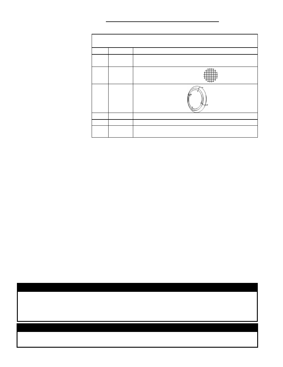
7.2.2 HORIZONTAL VENT TERMINAL Installation - Option CC6
Components Required - Factory and Field
Parts in the Horizontal
Vent/Combustion Air
Terminal Package
(Option CC6)
Complete Horizontal Vent/Combustion Air Terminal Kit (Same as Option
CC6), P/N 221247
Qty
P/N
Description
1
221069 Concentric Adapter Box with Silicone Sealing Ring (See
Paragraph 7.2.1.9, pages 16-17.)
1
221089 Bird Screen for Exhaust Outlet
1
124940 Ring Guard for Air Inlet
4
37661
#10-16x1/2" lg Screws to attach the inlet air guard
4
221186 Spacers for inlet air guard
1
221091 4" PVC Cap for Vent Condensate Drain Connection (See
FIGURE 8A and 9A on page 13.)
Field-supplied
requirements:
• Vent pipes and fittings as illustrated in
FIGURE 8A, 8B, 9A or 9B on pages 13
-14 and an elbow (22.5° elbow if available) as shown in
FIGURE 16, page 20
• Combustion air pipes (6” and 8” single-wall galvanized pipe)
• Flashing
• Sheetmetal screws, tape, primer, cement, and sealant as required
Before beginning, verify that the kit is at the site and that all components are
correct for the installation. Be sure all required field-supplied parts are available.
Installation Instructions
for Horizontal Vent/
Combustion Air Kit
Option CC6
(in compliance with
requirements on
pages 12-17)
1. Determine the location on the outside wall for the vent/combustion air
terminal. Location must comply with vent length requirement in Paragraph
7.2.1.4 on page 14. Also, read the “Hazards of Chlorine” on page 5 concerning
location of the combustion air inlet.
In most applications, the terminal will be on approximately the same level as the
heater. Allow for 1/4” per foot (6mm per 305mm)
downward pitch of the vent
pipe from the concentric adapter toward the heater for condensate to drain.
Minimum clearances for the horizontal vent terminal are shown in the table on
page 19. Avoid positioning the vent terminal above a walkway as there may be
a small amount of condensate that drips from the end of the vent/combustion air
terminal. In cold climates, the condensate may form icicles. Also, select a location
that complies with adjoining building clearances as shown in
FIGURE 16, page
20.
Products of combustion can cause discoloring of some building finishes and
deterioration of masonry materials. Applying a clear silicone sealant that is nor-
mally used to protect concrete driveways can protect masonry materials. If discol-
oration is an esthetic problem, re-locate the vent or install a vertical vent.
WARNING
All vent terminals must be positioned or located away from fresh air intakes, doors
and windows to preclude combustion products from entering occupied space.
Failure to comply could result in severe personal injury or death and/or property
damage.
WARNING
In climates with below freezing temperatures, condensate may form icicles on the
vent terminal. Locate the terminal where a falling icicle would not be a hazard.
7.2 Venting and
Combustion Air
(cont’d)
7.0 Mechanical
(cont’d)
Form I-UEAS, Page 18