0 mechanical (cont’d), 1 gas piping and pressure (cont’d) – Reznor UEAS Unit Installation Manual User Manual
Page 10
7.0 Mechanical
(cont’d)
7.1 Gas Piping and
Pressure (cont’d)
Derate by Valve Outlet
Pressure Adjustment for
High Altitude Operation
Instructions for High Altitude Derate
1. Determine the required valve outlet pressure for the elevation where the
heater will be operating. If unsure of the elevation, contact the local gas
supplier.
Altitude
Natural Gas
Propane
Feet
Meters
inches w.c.
Manifold Pressure Settings by Altitude for the UNITED STATES
0-2000
0-610
3.5
10.0
2001-3000
611-915
3.1
8.8
3001-4000
916-1220
3.0
8.5
4001-5000
1221-1525
2.8
8.1
5001-6000
1526-1830
2.7
7.7
6001-7000
1831-2135
2.6
7.4
7001-8000
2136-2440
2.5
7.1
8001-9000
2441-2745
2.4
6.7
9001-10000
2746-3045
2.2
6.4
Manifold Pressure Settings by Altitude for CANADA
0-2000
0-610
3.5
10.0
2001-4500
611-1373
2.8
8.1
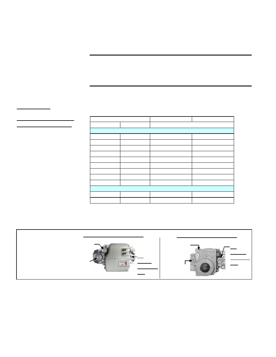
2. Locate the 1/8” output pressure tap on the valve (See FIGURE 6). Turn the
switch or knob on the top of the valve to “OFF”. Connect a manometer to the
1/8” pipe outlet pressure tap in the valve. Use a water column manometer that
is readable to the nearest tenth of an inch.
NOTE: This adjustment can
only be done after the heater
is in operation. High altitude
adjustment is included in the
startup procedures.
Valve Outlet Pressure
Settings by Elevation
3. Turn the switch or knob on the top of the valve to “ON”. Remove the cap
from the output pressure adjusting screw and adjust the gas train pressure
to the pressure selected from the table above. Adjust pressure by turning the
regulator screw IN (clockwise) to increase pressure or OUT (counterclockwise)
to decrease pressure.
4. Turn up the thermostat. Depress and hold the door safety switch. Cycle the
burner once or twice to properly seat the adjustment spring in the valve.
Re-check the pressure. When the outlet pressure is right for the installation,
remove the manometer and replace the cap.
Check for leak at the pressure tap fitting.
FIGURE 6 - Top
View of Valve
showing Outlet
Pressure Tap
and Adjustment
Locations
1/8”
Output
Pressure
Tap
Inlet
Pressure Tap
Output
Adjustment
Screw
Valve - UEAS 260 & 310
Valve - UEAS 130 & 180
1/8”
Outlet
Pressure
Tap
Inlet
Pressure
Tap
Adjust Outlet
Pressure
Normally when operating on natural gas at sea level, adjustments should
not be necessary to the factory setting. (For high altitude settings, see next
paragraph.)
If adjustment is necessary, remove the cap from the adjustment screw(s). Set
pressure to correct settings by turning the regulator screw IN (clockwise) to
increase pressure. Turn regulator screw OUT (counterclockwise) to decrease
pressure.
CAUTION: DO NOT bottom out the gas valve regulator
adjusting screw. This can result in unregulated manifold
pressure causing excess overfire and heat exchanger
failure.
Form I-UEAS, Page 10