0 controls -30, 1 thermostat 9.2 gas valve 9.3 safety controls, 0 controls – Reznor UEAS Unit Installation Manual User Manual
Page 29: 2 gas valve 9.3 safety controls, 1 thermostat, Danger
9.0 Controls
The main operating gas valve is powered by the 24-volt control circuit through the
thermostat and safety controls. The main control valve is a diaphragm type providing
regulated gas flow preset at the factory. (For location, see
FIGURE 28, page 37.)
9.2 Gas Valve
9.3 Safety Controls
9.3.1 Combustion Air Proving (Pressure Switch)
The combustion air proving switch is a pressure sensitive switch that monitors air
pressure to ensure that proper combustion airflow is available. The switch senses
the differential pressure between the negative pressure in the venter housing and
the pressure in the cabinet. (For switch location, see
FIGURE 28, page 37.)
On startup when the heater is cold, the sensing pressure is at the most negative
level, and as the heater and vent system warm up, the sensing pressure becomes
less negative. After the system has reached equilibrium (about 20 minutes), the
sensing pressure levels off.
If a restriction or excessive vent length or turns cause the sensing pressure to be
outside the switch setpoint, the pressure switch will function to shutoff the main
burner. The main burner will remain off until the system has cooled and/or the flue
system resistance is reduced.
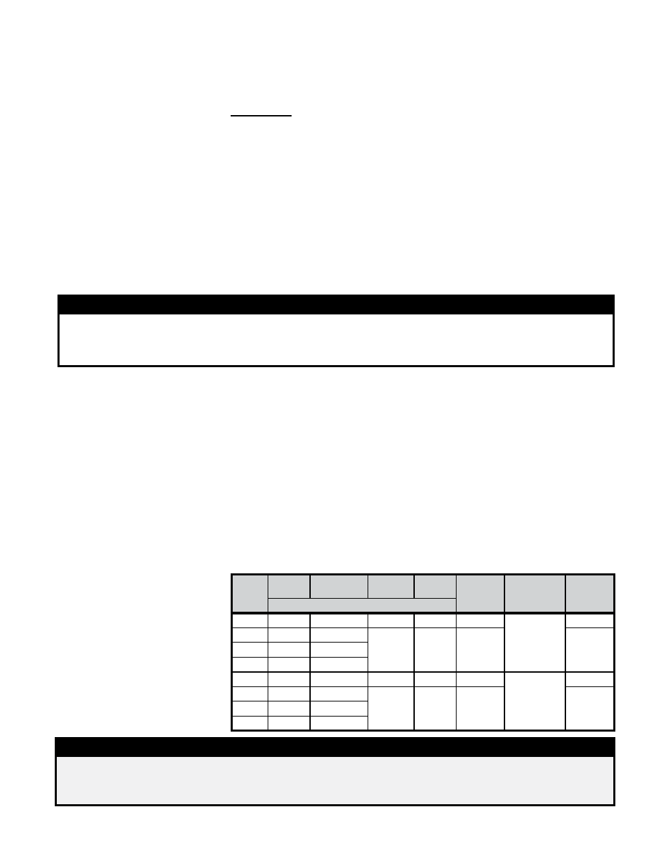
The Table below lists the approximate water column differential pressure readings
and switch setpoints for sea level operating conditions for Model UEAS heaters.
9.1 Thermostat
If the thermostat has an anticipator setting, make sure it is set to 0.6 amps (or in
accordance with the amperage value noted on the wiring diagram of your heater).
Make thermostat connections at the terminal strip on the back of the heater. The
strip has four terminals, G, W1, R, and W2; refer to the wiring diagram.
IMPORTANT: All units MUST be operated by a 24-volt thermostat. Never use a
line voltage disconnect switch as a means of operating the heater.
Multiple Heater Control, Option CL31 and Option CL32
-
If the heater was
ordered with a multiple heater control option, one thermostat can be used to control
up to six heaters. The option includes a 40VA transformer that replaces the stan-
dard transformer in the “controlling” unit and a relay assembly that attaches to the
additional unit. Option CL31 provides for control of two heaters. If control of addi-
tional heaters is desired (up to six total), Option CL32 which is the relay assembly
only must be added to each additional heater.
The option packages are shipped separately and include complete instructions on
installation and wiring.
Pressure Switch
Identification
DANGER
Safe operation of this unit requires proper venting flow. NEVER bypass combustion air
proving switch or attempt to operate the unit without the venter running and the proper flow
in the vent system.Hazardous conditions could result. See Hazard Intensity Levels, page 2.
Model
UEAS
Startup
Cold
Equilibrium
Hot
Setpoint
OFF
Setpoint
ON
Label
Color
Altitude
(FT.)
Switch
P/N
Differential Pressure Measured in " w.c.
130
3.0
2.8
2.65
2.75
Yellow
0 to 6,000
221251
180
3.1
2.8
2.30
2.91
Blue
221228
260
3.3
2.9
310
3.5
3.2
130
2.95
2.75
2.60
2.65
Green
6,001 to
10,000
235954
180
3.05
2.75
2.25
2.30
Orange
235953
260
3.25
2.85
310
3.45
3.15
WARNING
The operating valve is the prime safety shutoff. All gas supply lines must be free
of dirt or scale before connecting the unit to ensure positive closure. See Hazard
Levels, page 2.
Form I-UEAS, P/N 221232 R13, Page 29