2 clearances, 0 high altitude operation 6.0 hanging the heater – Reznor UEAS Unit Installation Manual User Manual
Page 7
4.2 Clearances
Clearances
Model UEAS
130, 180, 260,
310
Top
Flue Connector
Access Panel
Non-Access Side
Bottom*
Rear**
inches
mm
inches
mm
inches
mm
inches
mm
inches
mm
inches
mm
4
102
6
152
18
457
2
51
1
25
18
457
*Suspend the heater so that the bottom is a minimum of 5 feet (1.5M) above the floor.
** Measure rear clearance from the fan motor.
Units must be installed so that the clearances in the table are provided for combus-
tion air space, inspection and service, and for proper spacing from combustible
construction. Clearance to combustibles is defined as the minimum distance from
the heater to a surface or object that is necessary to ensure that a surface temper-
ature of 90°F (50°C) above the surrounding ambient temperature is not exceeded.
If the heater is being installed at an elevation above 2000 ft (610M), the input rate
will have to be derated. This is done by adjusting the valve outlet pressure. Adjust-
ing the valve outlet pressure is done after the heater is in operation; follow the
instructions in Paragraph 7.1.3. Capacities and inputs for derated units are also
listed in Paragraph 7.1.3.
5.0 High Altitude
Operation
6.0 Hanging the
Heater
Before suspending the heater, check the supporting structure to be used to verify
that it has sufficient load-carrying capacity to support the weight of the unit.
Model
UEAS -
Weights
Size
130
180
260
310
lbs
230
245
360
395
kg
104
111
163
179
WARNING
Unit must be level
for proper operation.
Do not place or add
additional weight
to the suspended
heater. Hazard
Levels, page 2.
WARNING
Check the supporting structure to be used to verify
that it has sufficient load carrying capacity to support
the weight of the unit. Suspend the heater only from the
threaded nut retainers or with a manufacturer provided
kit. Do NOT suspend from the heater cabinet.
When the heater is lifted for suspension, support the bottom of the heater with plywood or other appropriately placed
material. If the bottom is not supported, damage could occur. Before hanging, verify that any screws used for holding
shipping brackets were re-installed in the cabinet.
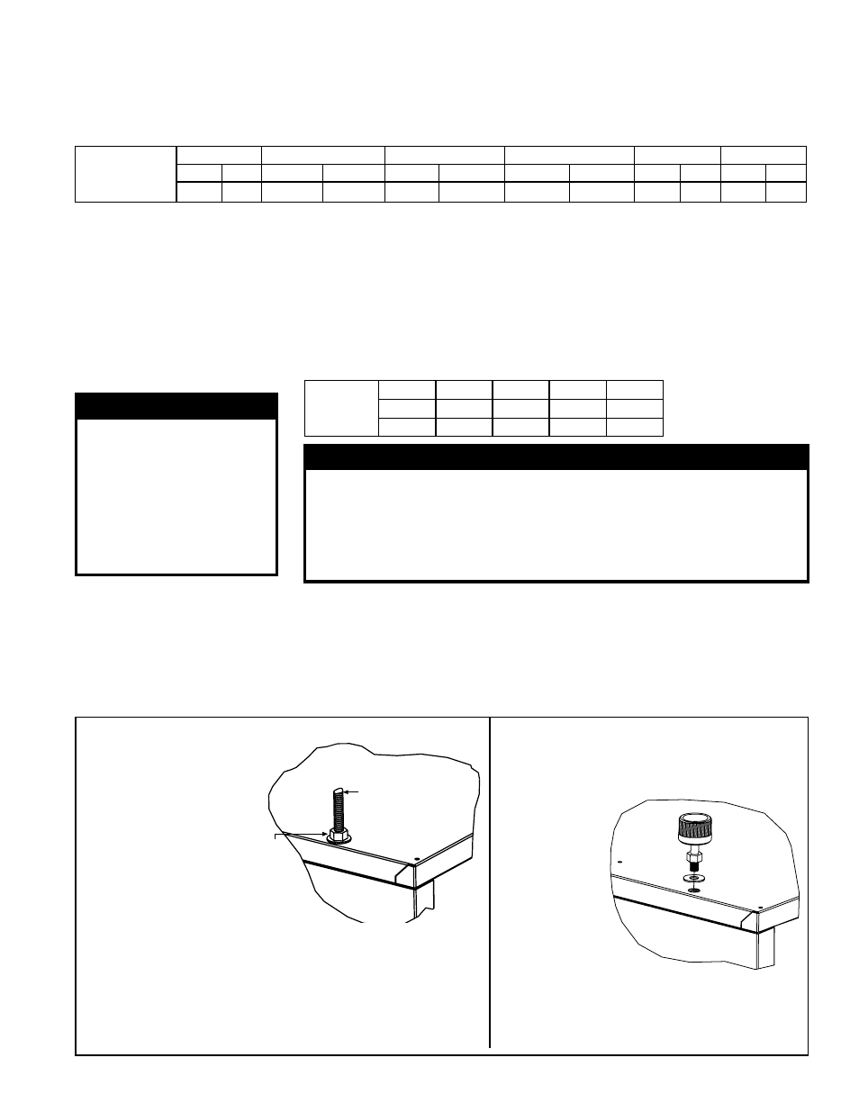
The heater has four-point suspension. Suspension point dimensions are shown in
FIGURE 2, page 6. A 3/8”-16 threaded
nut retainer is located at each suspension point (
FIGURE 4A).
If ordered with swivel connectors, Option CK10, for 1” pipe attach the swivels at the threaded nut retainers. Suspend
with 1” pipes (
FIGURE 4B).
FIGURE 4B - Swivel Connectors,
Option CK10, to Suspend the Heater
from 1” Pipes
Lock the swivel
connector to
the heater.
The connector
is threaded for
hanging from
a 1 pipe.
Add a 3/8 nut
and washer to
lock the hanger
rod to the heater.
3/8 threaded rod
(field supplied)
Be sure the threaded swivel
connectors are locked to the
heater as illustrated.
Be sure the threaded hanger rods are locked to
the heater as illustrated. Length of threaded rod
extending into the heater MUST NOT exceed 1/2”
(13mm).
Recommended maximum hanger rod length is 6
feet (1.8M).
FIGURE 4A - Suspending
the Heater with Rods
from the Threaded Nut
Retainers
Form I-UEAS, P/N 221232 R13, Page 7