2 venting and combustion air, 0 mechanical (cont’d), 1 gas piping and pressure (cont’d) – Reznor UEAS Unit Installation Manual User Manual
Page 12
7.1 Gas Piping and
Pressure (cont’d)
7.1.4 Converting from Natural Gas to Propane (cont’d)
7.2 Venting and
Combustion Air
All separated combustion units MUST BE equipped with both combustion air and
exhaust piping to the outdoors. The unique concentric adapter box required with
this heater allows for both combustion air and exhaust piping with only one hori-
zontal or vertical penetration hole in the building.
Concentric horizontal and vertical vent/combustion air systems (Option CC6 or
Option CC2) are the only venting/combustion air systems approved for high effi-
ciency Model UEAS separated-combustion unit heaters.
Model UEAS units are certified as Category IV heaters. These heaters are very
thermal efficient and will produce condensate during operation. The heater and
its venting system must be connected to a drain. See Paragraph 7.3, page 25, for
instructions on installing the condensate drain.
7.2.1.1 Types of Pipe
Provide field-supplied pipe in the types listed.
Vent Pipe - Schedule 40 PVC or CPVC pipe. In Canada, all PVC vent pipe must
be approved to ULC 636.
Combustion Air Inlet Pipe - Sealed, single-wall galvanized pipe is recommended
for the combustion air pipe.
7.2.1 Vent/Combustion
Air System
Requirements
7.0 Mechanical
(cont’d)
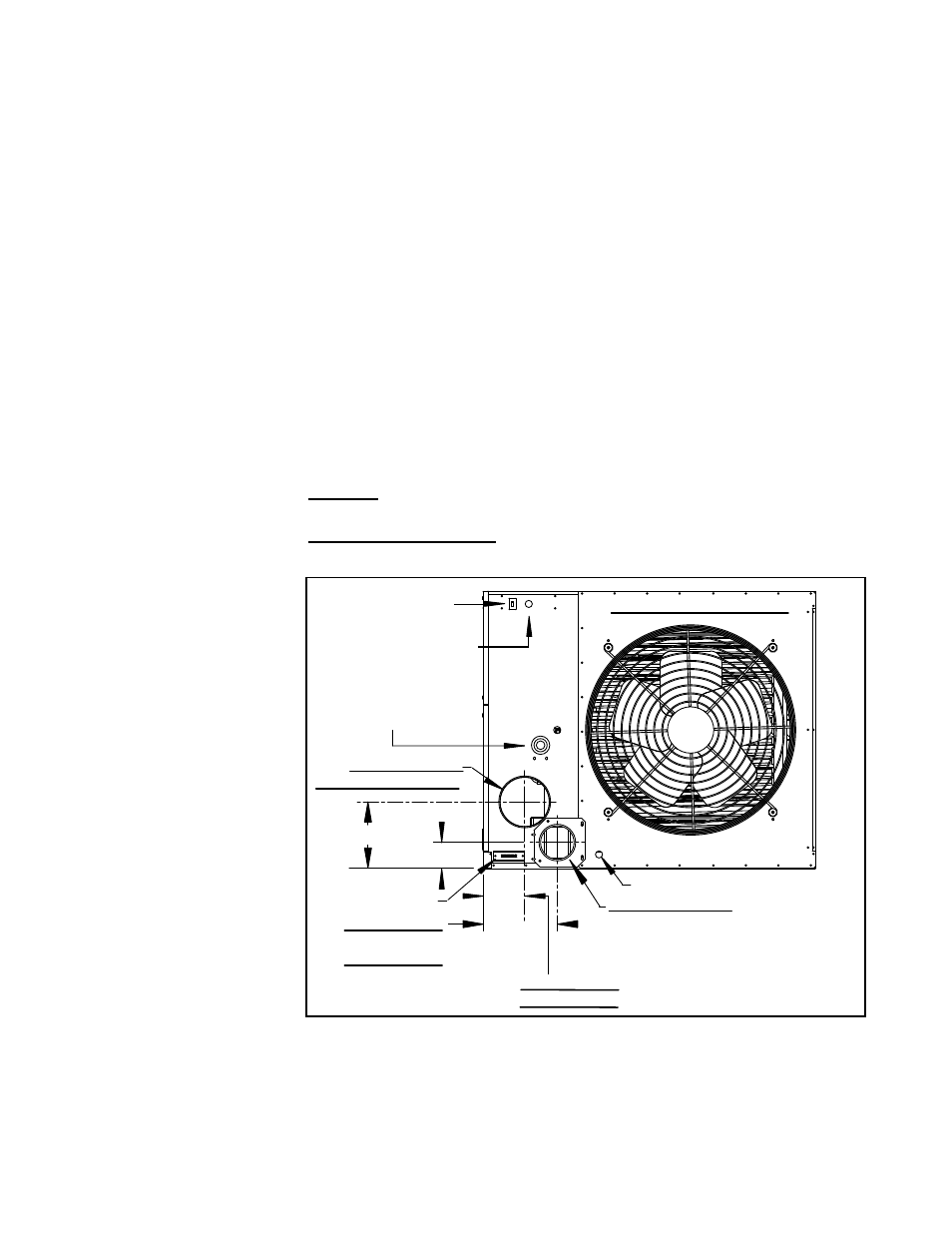
FIGURE 7 - Rear of a
Model UEAS Heater
showing the Locations
of Both Inlet Air
and Venter Outlet
Connections
Line Voltage Entrance
Gas Connection
(External)
6” dia Collar for
Combustion Air Pipe
Condensate Drain (1/2” PVC pipe)
4” PVC Vent Pipe (See vent conden-
sate drain requirements in FIGURE
8A, 8B, 9A ,or 9B and PVC joint
requirements in Paragraph 7.2.1.6.)
24V Terminal Strip
3-1/4” (83mm)
8-1/4” (210mm)
Sizes 130, 180; 4-5/16”(110mm)
Sizes 260, 310; 5-1/16”(129mm)
Sizes 130, 180;
8-5/16”(211mm)
Sizes 260, 310;
9-3/32”(231mm)
Rear View of Model UEAS
Disconnect Switch
7.2.1.2 Venter Outlet and
Combustion Air Inlet
7.2.1.3 Vent Condensate
Drain Connection
A condensate drain is required in the vent pipe. See
FIGURES 8A and 8B for
vertical vent or
FIGURES 9A and 9B for horizontal vent run with either horizon-
tal or vertical vent. For Canadian installation, refer to
FIGURE 8B or 9B only. In
Canada, all PVC vent pipe must be approved to ULC S636.
The 4” PVC cap with drain connection opening shown in
FIGURES 8A and 9A
is supplied with every heater. The drain connection, drain piping, and 4x4x4 PVC
vent pipe tee are field supplied. All of the vent and drain components shown in
FIGURES 8B and 9B are field supplied.
4. Fill in the information required on the gas conversion tape. Select a location
near the rating plate. Be sure the surface is clean and dry and affix the
conversion tape and propane label to the heater.
5. During heater startup, follow the instructions in Paragraph 7.1.3 to check the
valve outlet pressure.
Form I-UEAS, Page 12