0 maintenance and service (cont’d), 2 maintenance procedures (cont’d) – Reznor UEAS Unit Installation Manual User Manual
Page 38
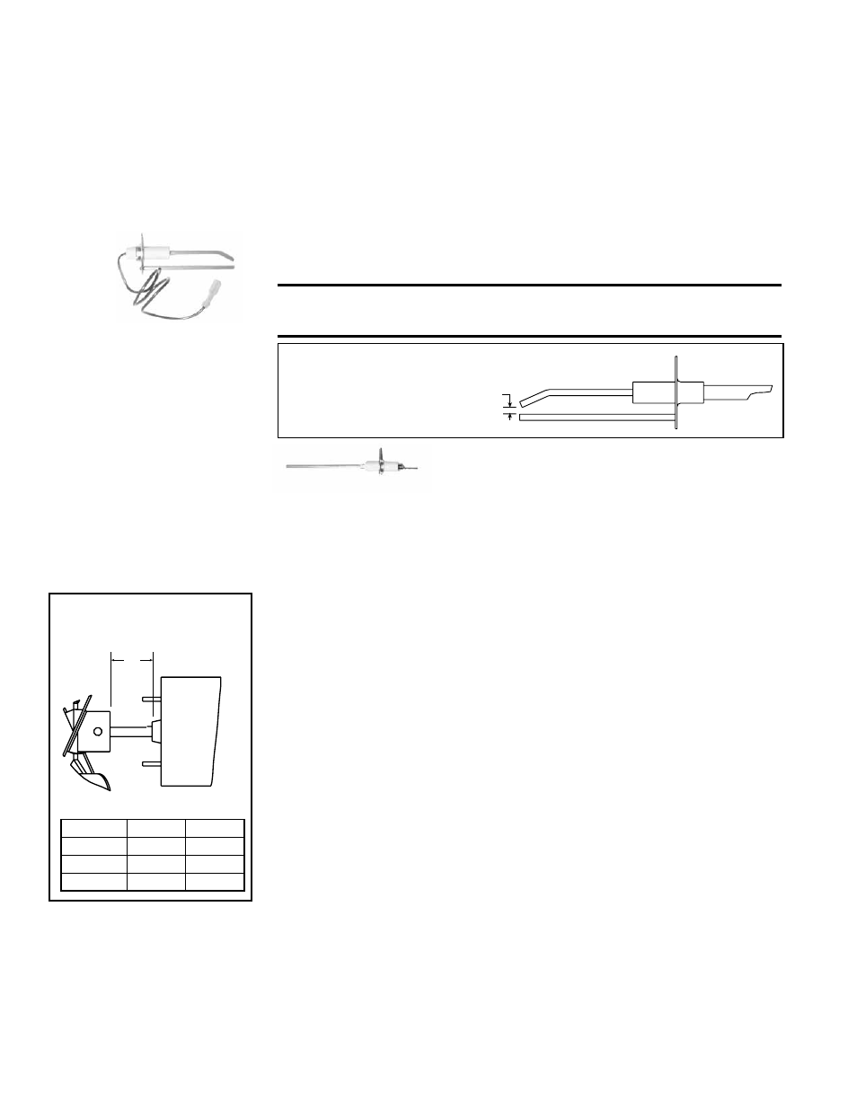
Ignitor - Refer to FIGURE 28 and locate the ignitor. Disconnect the wire; remove
the screw and the ignitor. Clean the ignitor assembly with an emery cloth.
Spark gap must be maintained to 1/8”. See
FIGURE 30.
IMPORTANT: When re-assembling, the brown ground wire must remain attached
to the ignitor.
CAUTION: Due to high voltage on the spark wire and electrode,
do not touch when energized. See Hazard Levels, page 2.
Ignitor
1/8 inch
(3.2mm)
Flame Sensor - Refer to FIGURE 28 and locate the
flame sensor. Disconnect the wire; remove the screw
and the flame sensor. Clean with an emery cloth.
Flame Sensor
12.2.5 Fan Motor, Fan
Blades, and Guard
Remove dirt and grease from the motor, the fan guard, and blades. Use care when
cleaning the fan blades to prevent causing misalignment or imbalance. Check that
the hub of the fan blades is secure to the shaft.
Follow these instructions for replacement of the fan guard, fan motor and/or fan
blades.
1. If the heater is installed, turn off the gas and disconnect the electric power.
2. Open the access door and disconnect the fan motor wires, capacitor wires at
the capacitor, and ground screw.
3. Remove the assembled parts (the fan guard, the motor and the fan blade).
4. Disassemble and replace whatever parts are needed and reassemble using
whatever part(s) are being replaced and the original parts.
Be sure the fan blade is in the proper position on the shaft; refer to the illustra-
tion and table in
FIGURE 31.
Position the assembly on the heater. Attach the fan guard.
Rotate the fan blade to check for adequate clearance. If adjustment is
required, loosen the mounting screws, re-position the fan guard, and tighten
the screws. Rotate the fan blade and re-check for adequate clearance.
Repeat this procedure until the assembly is positioned properly.
5. Reconnect the fan motor wires according to the wiring diagram and close the
access panel.
6. Restore power to the heater and turn on the gas. Light, following the instruc-
tions on the lighting instruction plate. Check for proper operation.
12.2.6 Venter Motor, Wheel, and Pressure Sensing Tap
Remove dirt and grease from the motor casing, the venter housing, pressure
sensing tap, and the venter wheel. Venter motor bearings are permanently lubri-
cated. Follow these instructions for replacement of the venter motor and wheel
assembly. Keep all hardware removed to be used in re-assembling and installing
the replacement parts.
12.2 Maintenance
Procedures
(cont’d)
FIGURE 30 - Ignitor showing required Spark
Gap Measurement
Dimension A
Size
inches
mm
130, 180
1-5/8
67
260
2
51
310
1-7/8
48
A
Fan
Motor
Fan
Blade
FIGURE 31 - Fan Blade
Position on the Shaft
12.0 Maintenance
and Service
(cont’d)
1. Turn off the gas and disconnect the electric power.
2. Open the burner/control compartment access panel.
Replacement
Instructions
Do not attempt to disassemble the control module. However, each heating season
check the lead wires for insulation deterioration and good connections.
Proper operation of the direct spark ignition system requires a minimum flame
signal of 1.0 microamps as measured by a microampmeter.
NOTE: For additional information and check out procedure on the direct spark
ignition system, refer to Paragraph 10 and the Troubleshooting Flow Chart in
Paragraph 12.3.
12.2.4. Ignition System (cont’d)
Form I-UEAS, Page 38