Combustion air pressure switch, Limit control, Warning – Reznor UEAS Unit Installation Manual User Manual
Page 39
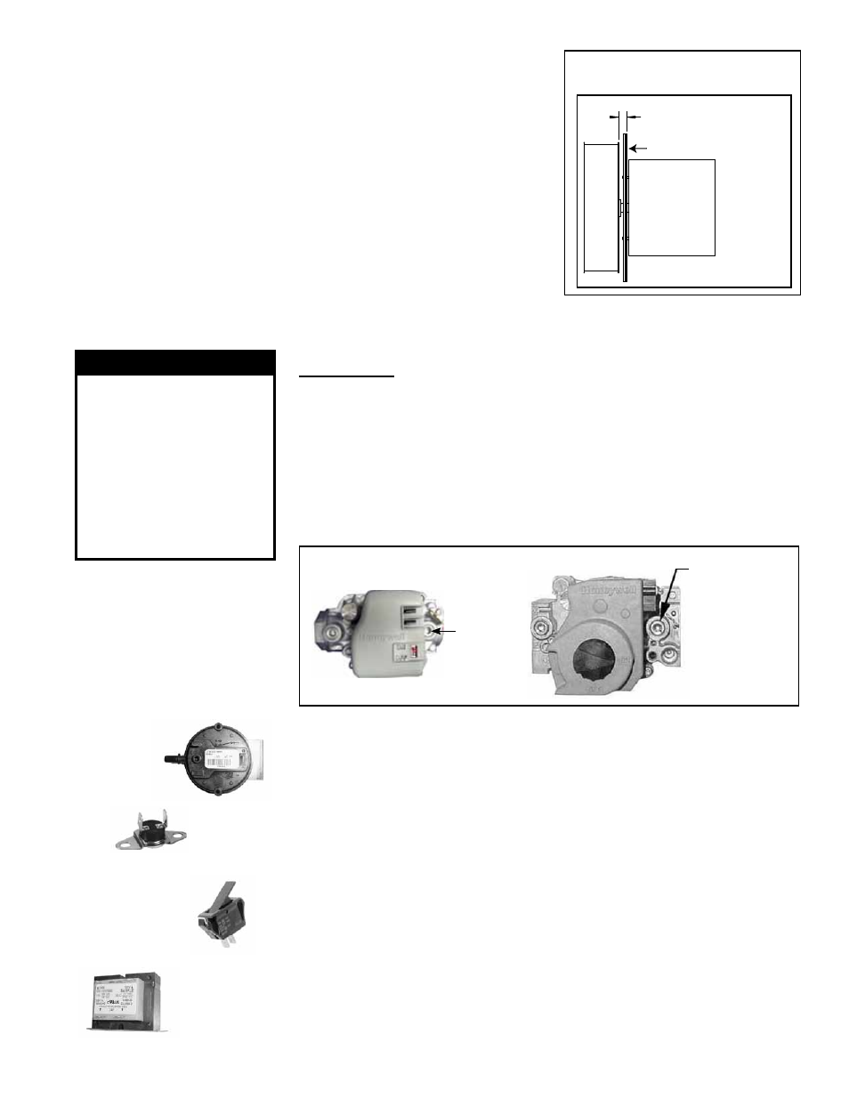
FIGURE 32 - Venter Wheel
Position on Shaft
1/2” (13mm) from
motor plate to wheel
Venter
Motor
Venter Wheel
Motor Plate with Gasket
WARNING
The operating valve
is the prime safety
shutoff. To ensure
positive closure, clean
all dirt and scale from
gas supply lines before
connecting to the unit.
See Hazard Levels,
page 2.
12.2.7 Operating Gas
Valve
NOTE: Operational pressure
settings and instructions for
checking pressure settings are
in Paragraph 7.1.3.
FIGURE 33 - Pressure
Tap for Checking Gas
Flow Shutoff
1/8” Outlet
Pressure Tap
Top Views of Two Styles of
Valves used on UEAS Units
Carefully remove external dirt accumulation and check wiring connections.
The combination gas valve must be checked annually to ensure that the valve is
shutting off gas flow completely.
Instructions:
1) Locate the 1/8” NPT pressure tap on the combination valve.
2) With the manual valve turned off to prevent flow to the gas valve, connect a
manometer to the 1/8” outlet pressure tap in the valve.
NOTE: A manometer
(fluid-filled gauge) is recommended.
3) Turn the manual valve to the ON position and the heater OFF. Use your
finger to fully block the main burner orifice for several seconds. Observe the
manometer with the orifice blocked, and if any pressure is indicated, the gas
valve is leaking.
A leaking gas valve must be replaced before the heater is
put back in operation
1/8”
Outlet
Pressure
Tap
12.2.8
Combustion Air Pressure Switch
See
FIGURE 28, page 37, for location. If it is determined that the pressure switch
needs replacing, use only the factory-authorized replacement part that is designed
for the model and size of heater being serviced.
Pressure
Switch
12.2.9
Limit Control
If it is determined that the limit control needs replacing, use only a factory-autho-
rized replacement part that is designed for the size of heater.
For approximate limit location, see
FIGURE 28, page 37.
Limit
Control
3. Disconnect the three venter motor wires at the DSI control, capacitor
wires at the capacitor (if applicable), and ground screw (located on the
control panel).
4. Holding the venter motor, remove the six screws that attach the venter
motor mounting plate to the venter housing. Remove the motor and
wheel assembly from the heater.
5. Re-assemble with the replacement venter motor and wheel assem-
bly. See
FIGURE 32. If the motor plate gasket is damaged, it must be
replaced.
6. Follow the wiring diagram to connect the venter wires.
7. Replace the access panel. Restore power to the heater and turn on the
gas. Light, following the instructions on the lighting instruction plate.
Check for proper operation.
12.2.10 Door Switch
If it is determined that the door switch needs replacing, use only a factory-autho-
rized replacement part that is designed for the heater.
Door
Switch
Transformer
12.2.11 Transformer
Use a voltmeter to verify that there are 24 volts output from the transformer.
If the transformer is not functioning, it must be replaced. Use a replacement
transformer identical to the factory-installed model.
Form I-UEAS, P/N 221232 R13, Page 39