0 unit heater location -5, Hx y z, 0 general (cont’d) – Reznor UEAS Unit Installation Manual User Manual
Page 4: 0 unit heater location, 4 installation codes (cont’d), Figure 1 - throw for fan model ueas heater throw, California warning label, Massachusetts requirement
1.0 General (cont’d)
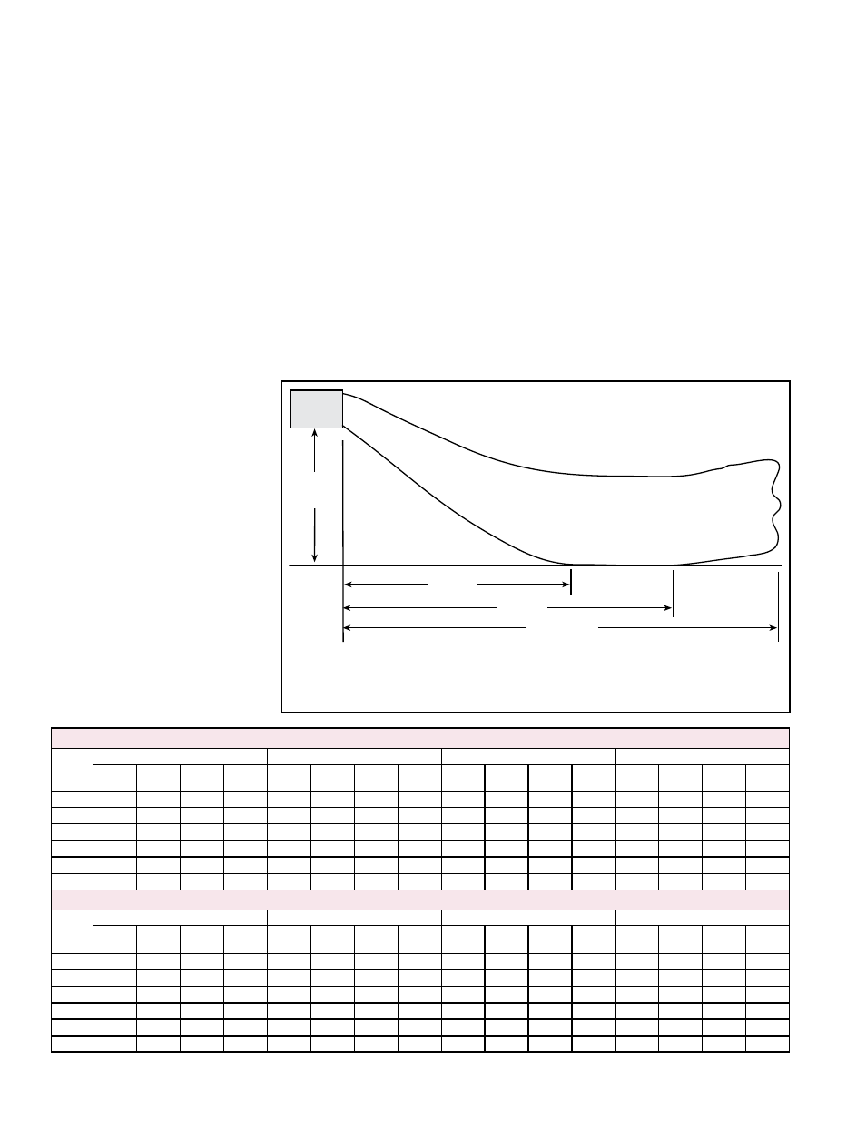
FIGURE 1 - Throw for
Fan Model UEAS
Heater Throw
2.0 Unit Heater
Location
H
X
Y
Z**
*Louver angle listed in the table is
relative to the top of the heater
.
H = Distance from bottom of heater to the floor
X = Distance from heater to start of floor coverage
Y = Distance to end of floor coverage
**Z = point when the air velocity drops below 50 ft (15.2M) per minute
NOTE: Throws listed are with
standard adjustable horizontal
louvers at the angles listed
(angle is relative to the top
of the heater). Throw pattern
changes with the addition of
optional vertical louvers and/or
downturn nozzles.
Dimensions X, Y, and Z (feet) Model UEAS with Standard Horizontal Louvers at Mounting Heights of 5 - 18 ft
H
130
180
260
310
X
Y
Z
Louver
Angle*
X
Y
Z
Louver
Angle*
X
Y
Z
Louver
Angle*
X
Y
Z
Louver
Angle*
8 ft
13
24
73
-26°
16
30
93
-20°
15
28
94
-24°
17
31
105
-20°
10 ft
14
24
69
-32°
17
31
91
-25°
16
28
89
-29°
18
32
103
-25°
12 ft
14
24
64
-39°
18
31
88
-30°
17
28
85
-34°
19
32
98
-30°
14 ft
14
22
59
-45°
19
30
84
-34°
17
27
80
-40°
20
32
95
-34°
16 ft
13
20
53
-51°
19
29
79
-39°
17
25
74
-45°
21
31
90
-38°
18 ft
11
17
44
-58°
19
28
74
-44°
16
24
66
-51°
20
30
85
-43°
Dimensions X, Y, and Z (meters) Model UEAS with Standard Horizontal Louvers at Mounting Heights of 1.5 - 5.5M
H
130
180
260
310
X
Y
Z
Louver
Angle*
X
Y
Z
Louver
Angle*
X
Y
Z
Louver
Angle*
X
Y
Z
Louver
Angle*
2.4 M
4
7
22
-26°
5
9
28
-20°
5
9
29
-24°
5
9
32
-20°
3.0 M
4
7
21
-32°
5
9
28
-25°
5
9
27
-29°
6
10
31
-25°
3.7 M
4
7
20
-39°
6
9
27
-30°
5
9
26
-34°
6
10
30
-30°
4.3 M
4
7
18
-45°
6
9
26
-34°
5
8
24
-40°
6
10
29
-34°
4.9 M
4
6
16
-51°
6
9
24
-39°
5
8
23
-45°
6
9
27
-38°
5.5 M
3
5
13
-58°
6
9
23
-44°
5
7
20
-51°
6
9
26
-43°
dance with the requirements of the enforcing authorities, and in public garages in
accordance with CSA B149 codes.
California Warning Label
If the heater is being installed in the state of California, the installer
MUST attach a
warning label on the outside of the access door. Find the California Warning label,
P/N 196977, in the plastic bag with this installation manual. Select a location on the
heater access panel. Be sure the surface is clean and dry and adhere the label.
Massachusetts Requirement
If the heater is being installed in the Commonwealth of Massachusetts, this unit
must be installed by a licensed plumber or licensed gas fitter.
Use the throw data and location information in this section; clearances and dimen-
sions in Paragraph 4; weights and hanging instructions in Paragraph 6; and piping,
venting, and condensate drain requirements in Paragraph 7, to determine where
to suspend the heater. Due to possible condensate freezing in the secondary heat
exchanger and/or condensate drain, this heater should not be used in an applica-
tion where the space temperature of the location is below 50°F.
1.4 Installation Codes
(cont’d)
Form I-UEAS, Page 4