0 maintenance and service (cont’d), 2 maintenance procedures (cont’d) – Reznor UEAS Unit Installation Manual User Manual
Page 36
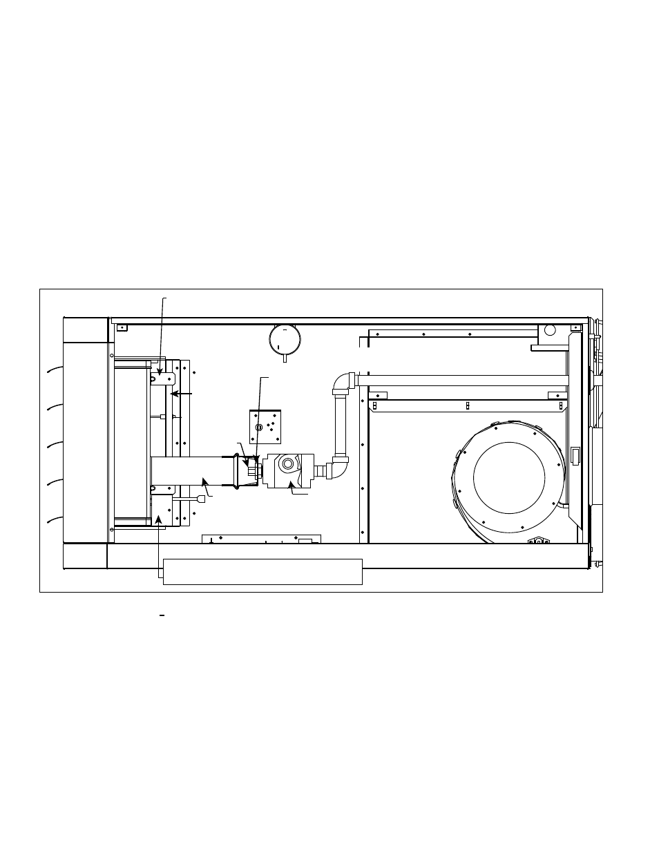
5. Disconnect and Move the Gas Train - At the gas valve, mark and disconnect
the wires. Carefully remove the burner orifice and orifice adapter locking nut.
Slide the orifice adapter out through the bracket on the burner pushing the gas
train to the right. This will move the gas train out of the way.
6. Remove Secondary Air Baffles) - Vertical along the right side of the burner,
locate the flat plate(s) identified as the secondary air baffle(s). The quantity of
baffles could be one to four depending on heater size. Each baffle is held in
place by one screw.
For re-assembly, on the secondary air shield, mark
the location (top and bottom) of each baffle. Remove all baffles.
7. Remove Burner Assembly
a) Locate the burner body supports. Depending on the size, the burner will
have two or more supports. At each support, remove the one screw that
attaches it to the secondary air shield
b) Holding the venturi tube, slide the entire burner assembly slightly to the
right to disengage the burner from the supports on the left. Then rotate the
open end of the venturi tube inward toward the heater. Carefully pull the
burner assembly out of the cabinet.
FIGURE 27 - Burner
Removal
Venter
Gas
Valve
Secondary
Air Shield
Burner Body Support (at least two per unit) - Remove screw attaching
to secondary air shield. Support remains attached to the burner.
Burner Assembly
Burner
Orifice
Orifice
Adapter
Locking Nut
Disconnect gas train at orifice and
outside the heater; slide to the right.
Venturi Tube
Slide right; rotate
inward; pull out.
Secondary Air Baffle (Qty varies per size.)
Mark locations before removing.
Inspect and Clean the
Burner
Inspect the Lower
Portion of the Heat
Exchanger (with burner
assembly removed)
12.2 Maintenance
Procedures
(cont’d)
12.2.2 Burner
Maintenance (cont’d)
12.0 Maintenance
and Service
(cont’d)
At the burner flame entrance of each tube, shine a bright light into each heat
exchanger section. With the light shining into the heat exchanger, observe the
outside for visible light. Repeat this procedure with each heat exchanger section.
If any light is observed, replace the heat exchanger.
With the burner assembly removed, shine a flashlight on the burner ribbons. Look
for carbon buildup, scale, dust, lint, and/or anything that might restrict flow through
the spaces between the burner ribbons. Holding the burner assembly so that any
foreign material will fall away from the burner, use a stiff bristle brush to loosen and
remove any foreign material(s). If the burner is excessively dirty, remove one of
the burner end caps. Remove the four screws that hold the end cap to the burner
housing. Lightly tap the end cap to remove it.
Clean all foreign material from the burner and venturi. After the burner is thor-
oughly clean, replace the end cap making certain that it is tight against the burner
housing.
NOTE: If any of the burner components are damaged or deteriorated,
replace the burner assembly.
Burner Removal Instructions (continued.)
Form I-UEAS, Page 36