Re-install the burner 12.2.3 burner orifice, Figure 28 - location of controls, Ignition system – Reznor UEAS Unit Installation Manual User Manual
Page 37
Instructions to Re-Install the Burner (Refer to FIGURE 27)
1. Attach the Burner Assembly - Holding the venturi tube, slide the entire
burner assembly into position. Align the supports on the left side with the slots
in the burner shield; sliding the supports into the slots. On the right, re-attach
each burner body support to the secondary air shield.
2. Attach the Secondary Air Baffles - Re-attach the secondary air baffles as
marked. Baffles may be different sizes and each
must be attached in the
correct location.
3. Attach the Control Assembly - Carefully slide the control assembly
into position. Re-attach with the same screws. Check to be sure all wire
connections are secure.
4. Attach the Gas Train - Slide the gas train so that the orifice adapter is through
the bracket. Fasten the gas train to the bracket with the locking nut. Install the
gas orifice. Re-connect the wires to the gas valve.
5. Close the access panel.
6. Reconnect the gas supply at the union outside of the cabinet. Leak test the
connection with leak detecting solution.
7. Turn on the electric and the gas. Check for proper operation.
Re-Install the Burner
12.2.3 Burner Orifice
Burner orifice usually only needs to be replaced when installing a gas conversion
kit. If ordering a replacement orifice only, give BTUH content and specific gravity of
gas, as well as the model and serial number of the unit. When removing or replac-
ing the burner orifice, be careful not to damage the venturi tube and/or the bracket.
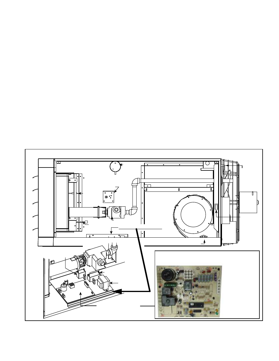
FIGURE 28 - Location of Controls
High Temperature
Limit Control
Gas Valve
Pressure
Switch
Venter
Vent Temperature
Limit Switch
Flame
Sensor
Ignitor
Fan
Motor
Control Panel Assembly
Door
Switch
Disconnect
Switch
Transformer
Fan Motor Capacitor
DSI Integrated Control
Module (Circuit Board)
Venter
Motor Capacitor
FIGURE 29 - DSI Integrated Control
Module (Circuit Board)
Only
replaceable
part is a Type
ATC or ATO
3 amp fuse
(Color Code
Violet),
P/N 201685
12.2.4. Ignition System
DSI Integrated Control Module (circuit board) - See FIGURE 29. The module
monitors the operation of the heater including ignition. The only replaceable com-
ponent is the 3 amp Type ATC or ATO fuse. If the fuse is blown, the problem is
most likely an external overload. Correct the problem and replace the fuse.
Form I-UEAS, P/N 221232 R13, Page 37