0 mechanical (cont’d), 2 venting and combustion air (cont’d), 2 horizontal vent terminal installation (cont’d) – Reznor UEAS Unit Installation Manual User Manual
Page 20
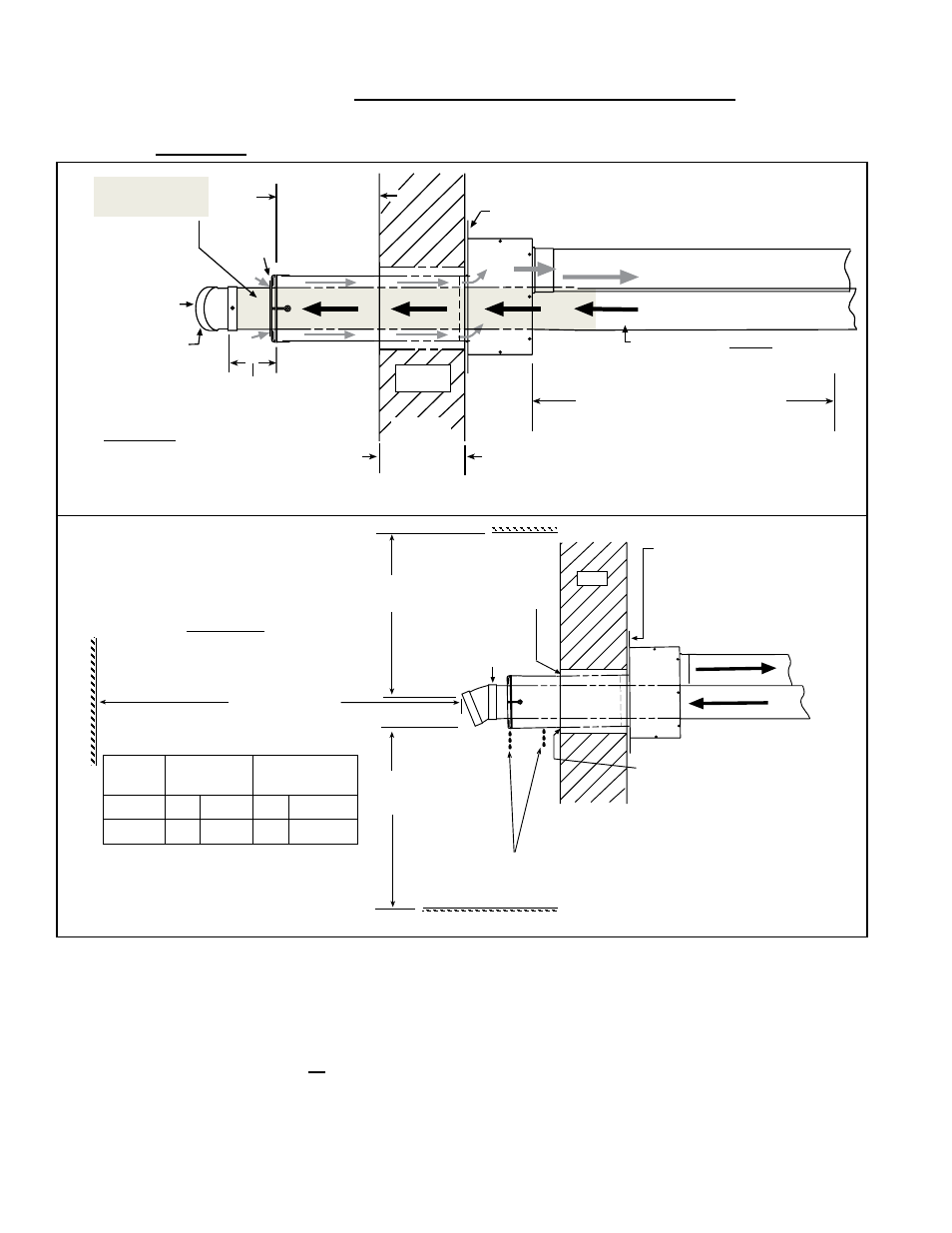
FIGURE 16 - Typical Installation of a Model UEAS High Efficiency, Separated-Combustion
Unit with a Horizontal Vent/Combustion Air Terminal (Option CC6)
Wall
Insert the Bird
Screen into the
socket of
the elbow.
Inlet Air
Guard
6 dia Single-Wall Metal Combustion
Air Pipe to Heater (seal joints)
4 dia CPVC or PVC Vent
Pipe Run from the Heater
Heater
Minimum distance between the
Concentric Adapter Box
and the Heater is 3 ft (9M).
Use the brackets on sides of box and field-supplied
hardware to attach the box to the inside wall.
One-piece, 4 dia,
Schedule 40 PVC
or CPVC Vent Pipe
Minimum
4 (102mm)
Maximum
16 (406mm)
1 (25mm
)
Minimum
48 (1219mm
)
Maximum
Minimum
3 (76mm)
Maximum
6 (152mm)
Pitch vent pipe toward the heater
1/4 per foot for condensate drain.
6 (152mm
)
Box Wid
th
*
Attach a 22.5°
Elbow to the end
of the vent pipe
with a sheetmetal
screw.
* A 90° or 45° elbow may be used
in place of the 22.5° elbow.
Top View
Use the brackets on
the sides of the box
and field-supplied
hardware to secure
the Concentric Adapter
Box to the inside wall.
Y
Minimum**
3 ft (1M)
Minimum
X - Minimum**
Adjoining Building
Building Projection
Building Overhang
[NOTE: Maximum overhang
is 24 (610mm).]
Wall
Rain water should drain out the
hole drilled in the bottom of the
pipe and/or the end of the pipe.
When sealing and/or flashing
around the combustion air pipe,
adjust so that the pipe has a slight
downward slope to prevent rain
water from running into the
concentric adapter box.
Flashing/
Sealing
(see right
below)
* 22.5° PVC Elbow
(attached at the
top with a
sheetmetal screw)
* A 90° or 45° elbow may be used in
place of the 22.5° elbow.
Side View
UEAS
Sizes
X
Y
130, 180 8 ft 2.4 M 36" 914 mm
260, 310 10 ft 3.0 M 48" 1219 mm
**Minimum - Check for and comply
with local Codes.
5. Attach the concentric adapter box to the wall.
Insert the combustion air pipe with inlet guard attached out through the wall.
Position the box so that the pipe is centered in the opening. Attach the brackets
to the wall with field-supplied hardware.
6. Determine length and install the “terminal-end” vent pipe.
6a) Determine length of pipe. The length of the continuous piece of terminal-
end vent pipe is determined by the installation within the maximum and minimum
requirements. See
FIGURE 16 to determine lengths of each segment and
calculate the total length required. The “terminal-end” vent pipe extending
through the box and concentric through the inlet air pipe must be one piece of
vent pipe without joints.
7.2.2 HORIZONTAL VENT TERMINAL Installation (cont’d)
7.2 Venting and Combustion Air (cont’d)
7.0 Mechanical
(cont’d)
Form I-UEAS, Page 20