7 support – Reznor UEAS Unit Installation Manual User Manual
Page 15
7.2.1.7 Support
2. Check for Proper Fit
With light pressure, test the fit. A dry pipe should go one-half to one-third of the
way into the fitting hub. Do not use pipe or fittings that are too tight or too loose.
3. Primer, Cement, and Applicator Requirements
a) Primer for joints should conform to ASTM F 656.
b) Cement for joints should conform to ASTM D 2564.
c) Use a 2-3” applicator brush for the 4” pipe and fittings.
4. Applying Primer and Cement (NOTE: Make joints one at a time as pipe and
fitting should be assembled quickly while cement is fluid.)
a) Apply primer to pipe and fitting surfaces. Do not allow primer to puddle
inside the system.
b) Apply a first coat of cement on the pipe O.D. Apply a full even layer of
cement for a distance slightly greater than the depth of the socket of the
coupler (fitting).
c) Coat the coupler (fitting) socket with a medium layer of cement, avoiding
puddling inside the system.
d) Apply a second full even layer of cement on the pipe O.D.
5. Join Pipe and Coupler (fitting)
Assemble pieces quickly while cement is fluid. Insert the pipe into the coupler
(fitting) until it touches the socket bottom. Turn the pipe a quarter turn. Hold the
joint together until the pipe will not pull out.
Clean excessive cement from the exterior. A properly made joint will have a
continuous bead of cement around the perimeter.
Vent Pipe Support - For continued safe operation, the vent system must be prop-
erly supported. A ten-foot (3M) length of PVC pipe weighs 20 pounds (9kg) and
has an expansion rate of four times that of metal pipe.
Horizontal CPVC or PVC vent must be supported every six feet (1.8M). The hang-
ers should provide as much bearing surface as possible and must be free of sharp
edges and burrs. Hangers must allow the pipe to expand laterally. Consider pipe
expansion when placing hangers. Changes in pipe direction will allow for expan-
sion. Hangers must be placed to allow for some direction movement. The slip joint
at the concentric adapter is designed to permit some limited expansion. DO NOT
USE THE HEATER OR CONCENTRIC ADAPTER BOX TO PROVIDE VENT PIPE
SUPPORT.
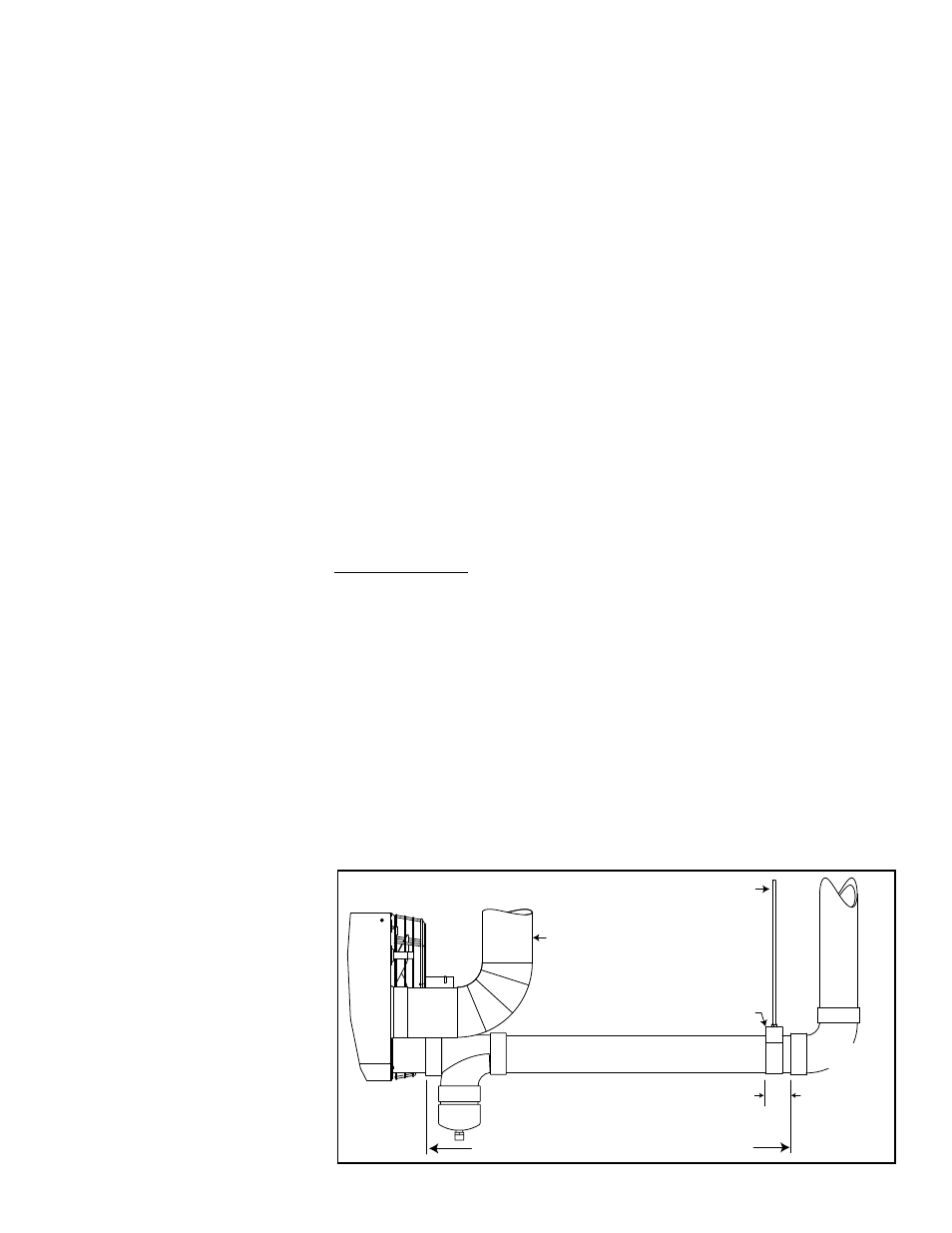
For a vertical CPVC or PVC vent, it is recommended that an engineer design the
vertical support system. An acceptable support for a simple vertical vent that is 30
feet (9.1M) or less and rises closely from the heater is illustrated in
FIGURE 10.
DO NOT USE THE HEATER OR CONCENTRIC ADAPTER TO PROVIDE VENT
PIPE SUPPORT.
FIGURE 10 - To allow for
expansion, use a field-
supplied cradle-type
vent pipe support
Cradle Support
3 to 6 inches
(76 to 152mm)
Maximum length 6 ft (1.8M) for single support
3/8” threaded rod
attached to building
structural member
Vertical single-wall
combustion air pipe may be
supported by the heater and
the concentric adapter box.
Model
UEAS
Vertical V
ent
Sweep-type
elbow only
Slope a horizontal run downward slightly
toward the vent condensate drain at the heater.
Form I-UEAS, P/N 221232 R13, Page 15