Cotinued) – Reznor UEAS Unit Installation Manual User Manual
Page 41
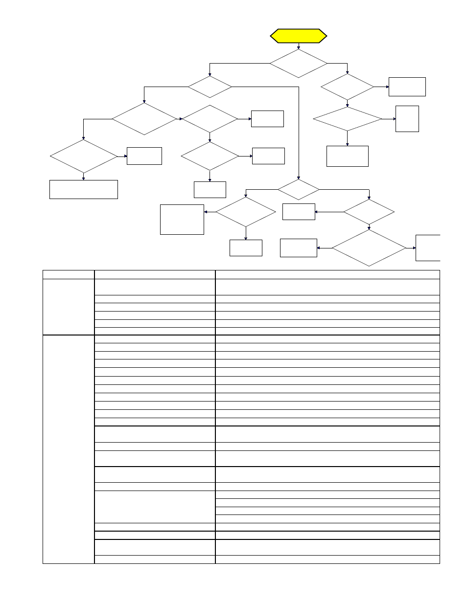
Trial for Ignition
Call for Heat
Is there a
spark across gap at
ignitor?
Does gas
ignite?
Is there minimum
flame current at the
flame sensor?
Is there
minimum flame current
at the control
module?
Replace control
module.
Check connections to flame
sensor and/or moisture in the
burner assembly.
Is the flame
sensor corroded?
Clean flame
sensor.
Is the sensor
located in flame
correctly?
Replace flame
sesnsor.
Reposition
flame sensor.
Is gas
flowing?
Is the ignitor
position correct in the
gas flow?
Check gas pressure
and supply voltage.
If either are low,
correct and repeat
startup.
Reposition
spark ignitor.
Is there
24VAC at the gas
valve?
Is there 24VAC
from gas valve output on
control module to
chassis?
Check wiring and
connections to
gas valve.
Replace
ignition
control
module.
Replace gas
valve.
Is there
spark voltage at
control?
Check high
voltage wire
continuity.
Is there 24V P1-2
to power control?
Replace
control
module.
Check wiring
and/or 24VAC
transformer output.
YES
NO
YES
NO
YES
NO
YES
NO
YES
NO
YES
NO
YES
NO
YES
NO
NO
YES
YES
NO
YES
NO
YES
NO
DSI Integrated Control Module
(Circuit Board) Trial
Troubleshooting
Flowchart
General Troubleshooting
PROBLEM
PROBABLE CAUSE
REMEDY
Venter motor
will not start
1. No power to unit.
1. Turn on power; check supply fuses or main circuit breaker. Turn on built-in
disconnect switch; replace switch if not operating.
2. No 24V power to integrated circuit board. 2. Turn up thermostat; check control transformer output.
3. Integrated circuit board fuse blown.
3. Correct cause. Replace fuse (type ATC or ATO, 32VDC, 3A).
4. No power to venter motor.
4. Tighten connections at circuit board and/or motor terminals.
5. Integrated circuit board defective.
5. Replace integrated circuit board.
6. Defective venter motor.
6. Replace venter motor. See Paragraph 12.2.6.
Burner will not
light
1. Manual valve not open.
1. Open manual valve.
2. Air in the gas line.
2. Bleed gas line (initial startup only).
3. Gas pressure too high or too low.
3. Supply pressure should be 5-14" w.c. for natural gas or 11-14" w.c. for propane.
4. No Spark:
4.
a) Loose wire connections.
a) Be certain all wire connections are solid.
b) Transformer failure.
b) Be sure 24 volts is available.
c) Incorrect spark gap.
c) Maintain spark gap at 1/8" (3.2mm).
d) Spark cable shorted to ground.
d) Replace worn or grounded spark cable.
e) Spark electrode shorted to ground.
e) Replace if ceramic spark electrode is cracked or grounded.
f) Burner not grounded.
f) Make certain integrated circuit board is grounded to ignitor.
g) Circuit board not grounded.
g) Make certain integrated circuit board is grounded to furnace chassis.
h) Unit not properly grounded.
h) Make certain unit is properly field grounded to earth ground and properly
phased (L1 to hot lead L2 to neutral).
i) Integrated circuit board fuse blown.
i) Correct cause. Replace fuse (type ATC or ATO, 32VDC, 3A).
j) Faulty integrated circuit board.
j) If 24 volt is available to the integrated circuit board and all other causes have
been eliminated, replace board.
5. Lockout device interrupting control circuit
by above causes.
5. Reset lockout by interrupting control at the thermostat or main power.
6. Interlock door switch open.
6. Close access door or replace switch.
7. Combustion air proving switch not
closing
7.
a) Make sure unit is properly vented.
b) Remove obstructions from vent.
c) Replace faulty tubing to pressure switch.
8. Faulty combustion air proving switch.
8. Replace combustion air proving switch.
9. Main valve not operating.
9.
a) Defective valve.
a) If 24 volt is measured at the valve connections and valve remains closed,
replace valve.
b) Loose wire connections
b) Check and tighten all wiring connections.
(cotinued)
Form I-UEAS, P/N 221232 R13, Page 41