Appendix -43, 0 maintenance and service (cont’d), Appendix – Reznor UEAS Unit Installation Manual User Manual
Page 42: 3 troubleshooting (cont’d), General troubleshooting (cont’d)
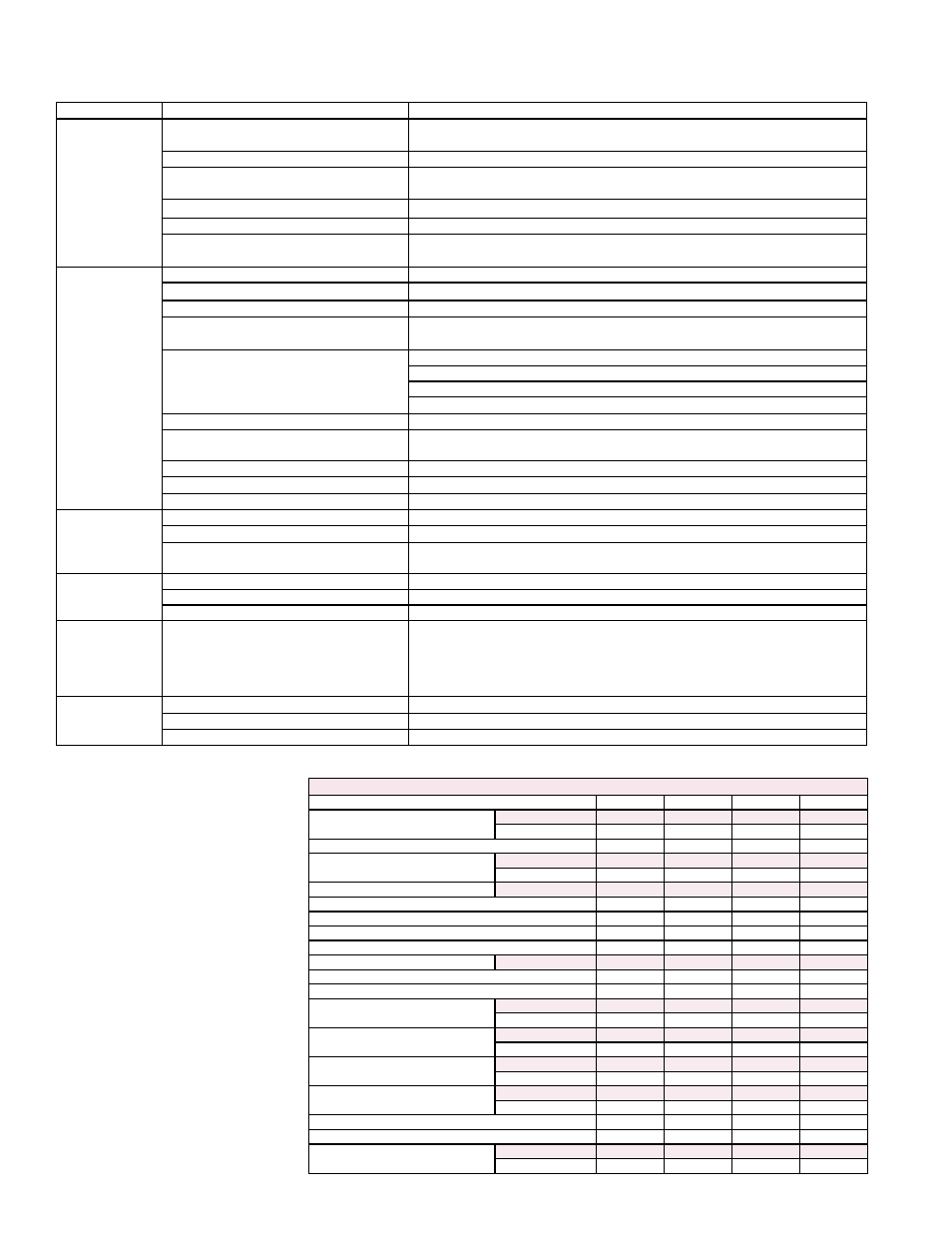
12.3 Troubleshooting (cont’d)
General Troubleshooting (cont’d)
12.0 Maintenance and
Service (cont’d)
PROBLEM
PROBABLE CAUSE (cont'd)
REMEDY (cont'd)
Burner will not
light (cont’d)
10. Integrated circuit board does not power
main valve.
10.
a) Loose wire connections.
a) Check and tighten all wiring connections.
b) Flame sensor grounded.
b) Be certain flame sensor lead is not grounded or insulation or ceramic is not
cracked. Replace as required.
c) Incorrect gas pressure.
c) Supply pressure should be 5-14” w.c. for natural gas or 11-14” w.c. for propane.
d) Cracked ceramic at sensor.
d) Replace sensor.
11. Faulty time delay relay. (applies to units
manufactured prior to 12/12)
11. Replace time delay relay.
Burner cycle on
and off
1. Gas pressure too high or too low.
1. Supply pressure should be 5-14” w.c. for natural gas or 11-14” w.c. for propane.
2. Burner not grounded
2. Make certain integrated circuit board is grounded to ignitor.
3. Circuit board not grounded.
3. Make certain integrated circuit board is grounded to furnace chassis.
4. Faulty integrated circuit board
4. If 24 volt is available to the integrated circuit board and all other causes have
been eliminated, replace board.
5. Combustion air proving switch not
closing
5.
a) Make sure unit is properly vented.
b) Remove obstructions from vent.
c) Replace faulty tubing to pressure switch.
6. Faulty combustion air proving switch.
6. Replace combustion air proving switch.
7. Flame sensor grounded.
7. Be certain flame sensor lead is not grounded or insulation or ceramic is not
cracked. Replace as required.
8. Cracked ceramic at sensor.
8. Replace sensor.
9. Incorrect polarity.
9. Reverse line volt leads to integrated circuit board.
10. Pin terminal loose on 9 pin plug.
10. Replace wire harness.
No heat (Heater
Operating)
1. Incorrect valve outlet pressure or orifice. 1. Check valve outlet pressure. See Rating plate for manifold pressure.
2. Cycling on limit control.
2. Check air throughput.
3. Improper thermostat location or
adjustment.
3. See thermostat manufacturer's instructions.
Fan or venter
motor will not
run
1. Circuit open.
1. Check wiring and connections.
2. Defective integrated circuit board.
2. Replace board.
3. Defective motor.
3. Replace motor.
Fan or venter
motor turns
on and off
while burner is
operating
1. Motor overload device cycling on and off. 1. Check motor load against motor rating plate. Replace motor if needed.
Fan or venter
motor cuts out
on overload
1. Low or high voltage supply.
1. Correct electric supply.
2. Defective motor.
2. Replace motor.
3. Poor airflow.
3. Clean motor, fan, and fan guard.
APPENDIX
TECHNICAL DATA
Model UEAS
130
180
260
310
Input Heating Capacity
BTUH
131,000
175,000
260,000
305,000
kw
38.4
51.2
76.1
89.3
Thermal Efficiency (%)
93
91
92
91
Output Heating Capacity
A
BTUH
121,830
159,250
239,200
277,550
kw
35.7
46.6
70.0
81.3
Gas Connection (inches)
B
Natural or Propane
1/2
1/2
3/4
3/4
Vent Connection Diameter (inches)
4
4
4
4
Combustion Air Inlet Diameter (inches)
6
6
6
6
Control Amps (24 volt)
1.0
1.0
1.0
1.0
Full Load Amps (115 volt)
6.3
6.3
10.0
10.0
Maximum Over Current Protection
C D
Standard 115V
15
15
20
20
Normal Power Consumption (watts)
657
657
1020
1020
Discharge Air Temperature Rise (°F)
50
60
50
60
Air Volume
CFM
2256
2458
4430
4283
M
3
/Minute
63.9
69.6
125.4
121.3
Discharge Air Opening Area
ft
2
2.6
2.6
4.8
4.8
M
2
0.2
0.2
0.5
0.5
Outlet Velocity
FPM
883
962
924
894
M/Minute
269
293
282
272
Fan Motor HP
D
Standard Open
1/4
1/4
1/2
1/2
Optional Enclosed
1/4
1/4
1/2
1/2
Fan Motor RPM
1050
1050
1050
1050
Fan Diameter (inches)
18
18
24
24
Approximate Condensate per Hour
Gallons
1
1
2
2
Liters
4
4
8
8
A
CSA ratings for altitudes to 2000 ft.
B
Size shown is for gas connection to a single-
stage gas valve, not supply line size.
C
MOCP = 2.25 x (largest motor FLA) +
smallest motor FLA. Answer is rounded to the
nearest available standard circuit breaker size.
D
Except where indicated, information in this
table is based on a heater equipped with a
standard 115 volt open fan motor.
Form I-UEAS, Page 42