Index – Reznor UEAS Unit Installation Manual User Manual
Page 43
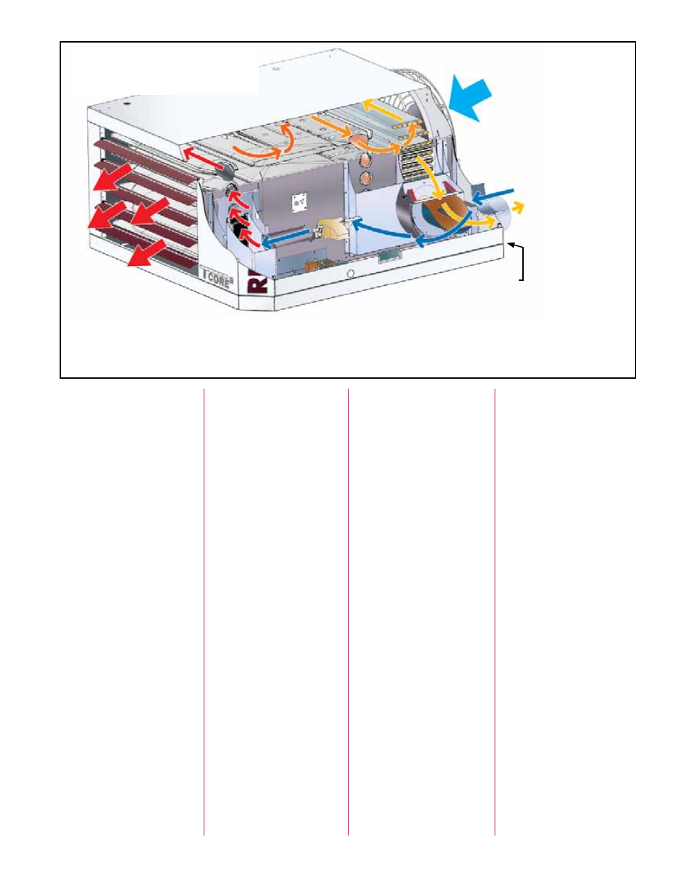
Operating Principle showing
Combustion Airflow and
Supply Airflow
This unit heater is a high efficiency appliance designed to extract part of the latent heat from the products of combustion. This
process forms condensation which is collected and directed to a drainage point inside the unit. The heater is equipped with a 1/2”
(12.7mm) PVC pipe for connecting to a condensate drain. The water condensed from the products of combustion will be acidic.
The level of concentration is dependent upon the environment where the appliance is installed and may be as high as 6PH. DO
NOT USE COPPER OR COPPER BASED ALLOYS FOR CONDENSATE DRAINS.
Room Supply
Air Intake
Warm
Air
Discharge
Flue Gas Outlet
Cooler flue gas tem-
perature requires a
condensate drain in
the vent.
Condensate
drain connection from
the secondary heat exchanger
Outside
Combustion Air
to the Burner
INDEX
A
Abnormal Heat Cycle Functions
B
Burner Removal Instructions
C
California Warning Label 4
Check Installation After Startup
Check the Installation Prior to
Combustion Air Inlet 12
Combustion Air Inlet Pipe 12
Combustion Air Pipe Support
Combustion Air Pressure
Combustion Air Proving
Concentric Adapter Box
Concentric Adapter Box
Condensate Drain Traps 25
D
Derate by Valve Outlet
DSI Integrated Control Module
E
F
Fan/Blower OFF Delay Settings
G
Gas Valve 29, 34, 39
H
HAZARD INTENSITY LEVELS
Normal Heat Cycle Operating
Heat Exchanger Maintenance
High Altitude 7
High Altitude Capacity 11
High Altitude Derate 10
Horizontal Vent/Combustion Air
Horizontal Vent/Combustion Air
I
J
L
M
O
P
Pressure Sensing Tap 38
Pressure Switch Identification
S
T
Heater Throw 4
U
V
Valve Outlet Pressure Settings
Vent/Combustion Air System
Vent Temperature Limiting
Vent Temperature Limit Switch
Vertical Vent/Combustion Air Kit
Vertical Vent/Combustion Air
W
Form I-UEAS, P/N 221232 R13, Page 43