Reznor UEAS Unit Installation Manual User Manual
Page 13
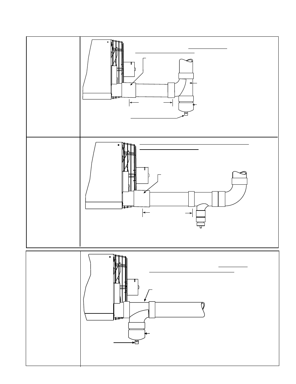
Installer-provided
4x4x4 PVC Sweep
or Sanitary Tee
4 PVC Cap is included in the vent/
combustion air kit(OptionCC2). Cap
is drilled and tapped for field-supplied
1/2 NPT condensate drain.
Field-supplied Drain Fitting
Both the vent condensate drain and the heat exchanger condensate drain require a trap and must go into a sanitary
drain. (See Paragraph 7.3, pages 25-26, for requirements on installing the condensate drain.) All drain parts except the
4 PVC cap shown here are field supplied.
Model
UEAS
Installer-provided
4 Coupling
Slope downward
away from the
heater.
4 diameter
pipe
12 (305mm)
minimum
24 (610mm)
maximum
THIS PVC PIPING ARRANGEMENT APPLIES TO
U.S. INSTALLATIONS ONLY; IT DOES NOT APPLY
TO CANADIAN INSTALLATIONS.
Balance of the vent may be
either horizontal or vertical.
Slope a horizontal run down-
ward slightly toward the vent
condensate drain at the heater.
Attach installer-provided 4x4x4
PVC Tee to the 4 vent pipe outlet.
4 PVC Cap is included in the vent/combustion air kit
(Option CC2 or CC6). Cap is drilled and tapped for
field-supplied 1/2 NPT condensate drain.
Field-supplied
Drain Fitting
Both the vent condensate drain and the heat exchanger condensate drain require a trap and
must go into a sanitary drain. (See Paragraph 7.3, pages 25-26, for requirements on installing the
condensate drain.) All drain parts except the 4 PVC cap shown here are field supplied.
Model
UEAS
THIS PVC PIPING ARRANGEMENT APPLIES
TO U.S. INSTALLATIONS ONLY; IT DOES NOT
APPLY TO CANADIAN INSTALLATIONS.
FIGURE 9A - U.S.
INSTALLATION
ONLY -
Horizontal or
Vertical Vent
showing Where
to Install the
Condensate
Drain
Connection in
the Horizontal
Vent Run using
factory-provided
4” PVC Cap
12” (305mm)
minimum
24” (610mm)
maximum
Installer-provided 4” Coupling
Slope downward away from
the heater.
Model
UEAS
Field-supplied Fittings as
needed for 1/2” or larger
condensate drain line
Both the vent condensate drain and the heat exchanger condensate drain require a trap and
must go into a sanitary drain. (See Paragraph 7.3, pages 25-26, for requirements on installing
the condensate drain.) All vent and drain parts in this illustration are field supplied.
THIS PVC PIPING ARRANGEMENT APPLIES TO ALL
CANADIAN INSTALLATIONS. In Canada, all PVC vent pipe must
be approved to ULC S636. All PVC venting and drain parts in
this illustration are field supplied. This is an acceptable alternate
PVC piping arrangement for installations in the United States.
4” diameter pipe
FIGURE 8B -
CANADIAN
OR U.S.
INSTALLATION
Vertical Vent
showing Where
to Install the
Condensate
Drain
Connection
FIGURE 8A - U.S.
INSTALLATION
ONLY - Vertical
Vent showing
Where to Install
the Condensate
Drain
Connection
using factory-
provided 4”
PVC Cap
See Paragraph 7.2.1.6, page 14, for making vent pipe joints.
The vent pipe drain connects into the heater condensate drain. Refer to Paragraph
7.3, page 25, for condensate drain installation instructions.
Form I-UEAS, P/N 221232 R13, Page 13