3 condensate drain system – Reznor UEAS Unit Installation Manual User Manual
Page 25
7.3 Condensate Drain
System
The installer must provide a condensate drain system. A 4” PVC cleanout cap
(
FIGURE 22) that is drilled and tapped for a 1/2” NPT fitting is furnished with the
heater for the vent drain. All other material must be field supplied.
During operation, condensate is both produced in the heater and collected from
the venting system. Therefore, the installation requires a condensate drain from
the secondary heat exchanger (
FIGURE 21) and a condensate drain from the vent
pipe (
FIGURE 22).
CAUTION: Apply general plumbing practices if pipe
insulation or heat tapes are required to prevent freezing
of the condensate drain system.
For safe performance of the heater, each condensate drain must include a trap as
shown in
FIGURES 21 and 22.
Downstream from the traps the condensate drains may be joined and both must
be connected to a sanitary drain within the building. Check codes to be certain that
this is permitted. (Condensate from the heater has a ph of 6 and is not harmful to
a sanitary drain.
NOTE: Actual ph may vary ± 1 depending upon fuel and combus-
tion air.) Model UEAS Sizes 130 and 180 will produce approximately one gallon (4
liters) of condensate per hour. Sizes 260 and 310 will produce approximately two
gallons (8 liters) of condensate per hour.
A condensate disposal system that relies on gravity should be satisfactory for most
installations since unit heaters are normally installed several feet above the floor.
If a gravity system is not possible, a condensate pump may be installed. There
are a number of commercially available pumps made for this purpose. If using a
condensate pump, follow the pump manufacturer’s installation recommendations.
Condensate Drain Traps
Two condensate drain traps are required.
• FIGURE 21 illustrates the trap in the drain attached
to the heater and lists the minimum required leg
dimensions for that trap.
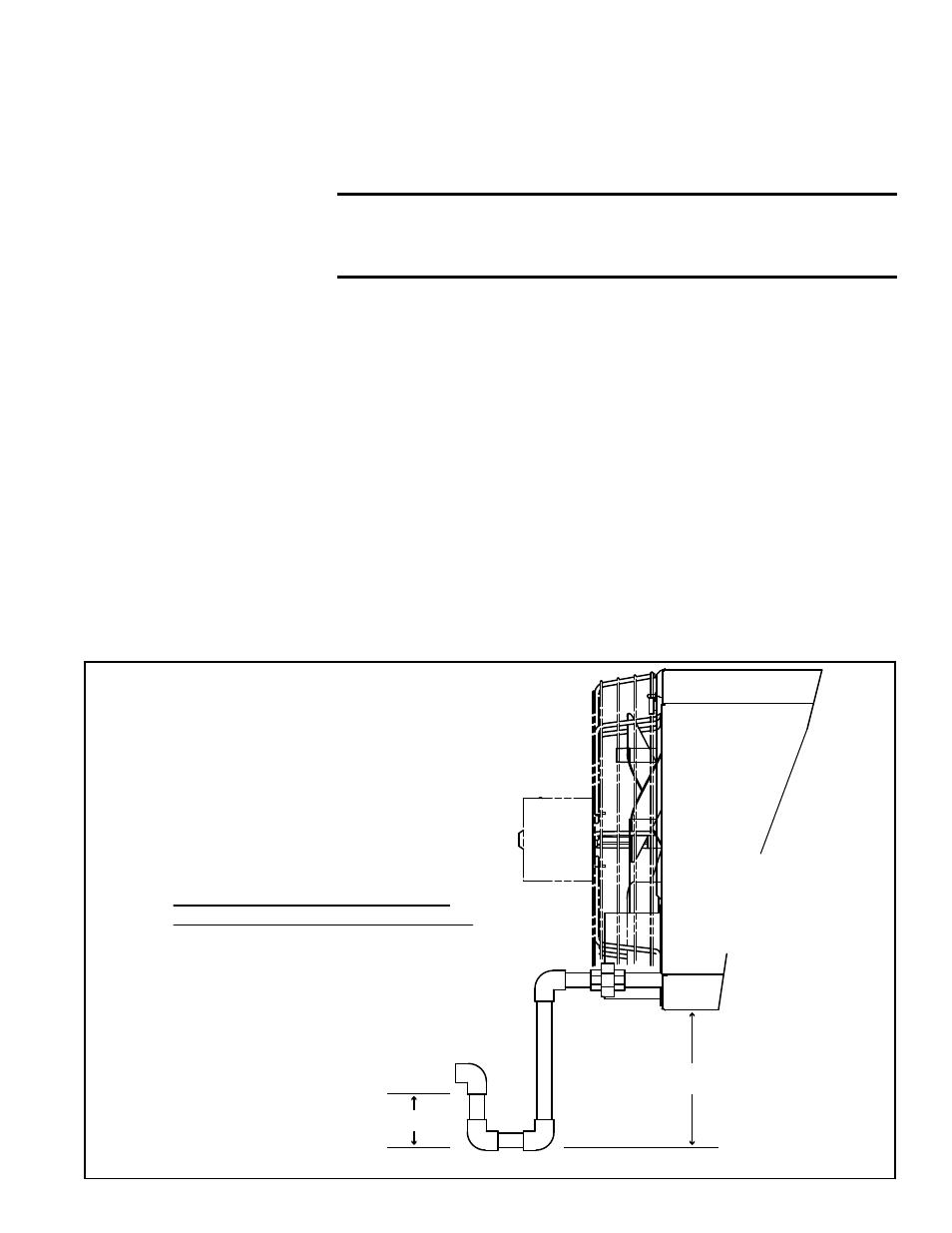
FIGURE 21 - Secondary Heat
Exchanger Condensate Drain Trap
Model UEAS
HEATER
Minimum Dimensions for Secondary
Heat Exchanger Condensate Drain Trap
“A” = 3 inches (76mm) minimum
“B” = “A” plus at least 5 inches (127mm)
Use 1/2” PVC pipe or larger for condensate drain.
Drain Trap
Continue into sanitary drain.
“A”
“B”
NOTE: Bottom of fan guard
is removed for better view.
See Rear View in
FIGURE 2,
page 6, for location of
condensate drain connection.
Form I-UEAS, P/N 221232 R13, Page 25