Clearances to horizontal vent terminal – Reznor UEAS Unit Installation Manual User Manual
Page 19
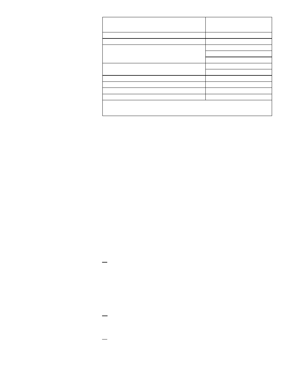
Clearances to Horizontal
Vent Terminal
Structure
Minimum Clearances for Vent
Terminal Location (all directions
unless specified)
Forced air inlet within 10 ft (3.1M)*
3 ft (0.9M) above
Combustion air inlet of another appliance
6 ft (1.8M)
Door, window, or gravity air inlet (any building opening)
4 ft (1.2M) horizontally
4 ft (1.2M) below
1 ft (305mm) above
Electric meter, gas meter ** and relief equipment
U.S. - 4 ft (1.2M) horizontally
Canada - 6 ft (1.8M)
Gas regulator **
3 ft (0.9M) horizontally
Adjoining building or parapet
6 ft (1.8M)
Adjacent public walkways
7 ft (2.1M) above
Grade (ground level)
3 ft (0.9M) above***
*Does not apply to the inlet of a direct vent appliance. **Do not terminate the vent directly above
a gas meter or service regulator. *** Consider local snow depth conditions. The vent must be at
least 6” (152mm) higher than anticipated snow depth.
2. Install the vent pipe and combustion air pipe runs (from the heater to
near the location selected through the wall).
• Use the type of pipe specified in Paragraph 7.2.1.1, page 12.
• Comply with the requirements in Paragraph 7.2.1.2 and 7.2.1.3, pages
12-14, when attaching pipes to the heater and installing the condensate drain
connection in the vent.
• Overall vent length must comply with the table in Paragraph 7.2.1.4, page 14.
• Make all joints according to the instructions in Paragraph 7.2.1.6, pages 14-15.
Extend the runs close to the wall location selected in Step 1 above. Provide
1/4” per foot (6mm per 305mm) downward pitch of the vent pipe toward the
heater for condensate to drain (
NOTE: The vent pipe will extend through the
wall after the concentric adapter box is installed. The indoor combustion air
pipe will end at the concentric adapter box.)
• Support pipes as required in Paragraph 7.2.1.7, pages 15-16.
3. Prepare a 9” diameter clearance hole through the outside wall for the 8”
diameter combustion air pipe.
Outside wall construction thickness should be 1” (25mm) minimum and 48”
(1219mm) maximum. Position the box against the wall. Being sure that the loca-
tion and box orientation are correct, mark the location where the combustion air
pipe will extend through the wall. Cut a 9” diameter hole so that the 8” pipe will be
centered through the 9” opening.
4. Prepare the concentric adapter box.
4a) Determine the length of the 8” diameter combustion air pipe and attach
it to the box.
Comply with the requirements in
FIGURE 16. Determine the length of the pipe
by measuring the wall thickness,
plus 4 to 16” (102-406 mm) beyond the wall,
minus the width of the pipe crimp which will be cut off.
So that the 8” inlet air guard will fit properly, cut the crimp off the end of the com-
bustion air pipe. Turn the combustion air pipe so that the seam will be toward the
top side of the box and slide it on the collar. Attach the combustion air pipe to the
collar with sheetmetal screws. Seal the joint and seam with sealant or tape.
4b) Drill a drain hole. On the bottom side of the pipe, mark a location that will be
outside between the end of pipe and the building (about 2/3 of the distance from
the end of the pipe to the edge of the building) when the box is installed. Drill a
1/2” diameter drain hole in the pipe at that location.
4c) Attach the inlet air guard. Position the inlet air ring guard over the end of
the combustion air pipe. See
FIGURE 16. Attach the guard to the inlet air pipe
with the four 1/2” long screws provided.
Form I-UEAS, P/N 221232 R13, Page 19