0 mechanical (cont’d), 2 venting and combustion air (cont’d) – Reznor UEAS Unit Installation Manual User Manual
Page 22
1. Determine the location of the vent terminal.
Select a location away from fresh air intakes, allowing space for the concentric
adapter box inside. Vent terminal must be located from adjacent buildings as
shown in
FIGURE 20, page 24.
WARNING
All vent terminals must be positioned or located away
from fresh air intakes, doors and windows to preclude
combustion products from entering occupied space.
Failure to comply could result in severe personal injury
or death and/or property damage.
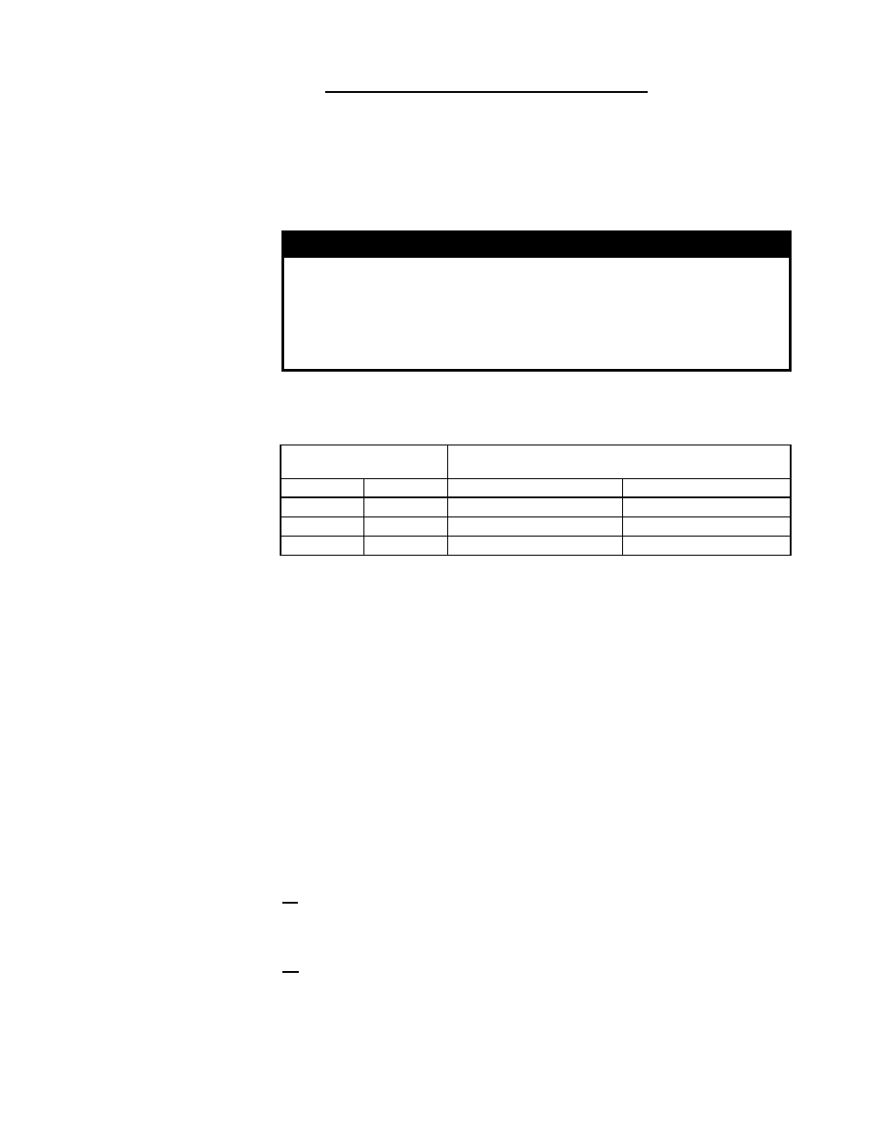
If more than one vertical concentric vent/combustion air terminal (Option CC2) is
being installed, the minimum spacing between vent centerlines is determined by
the minimum outdoor design temperature (most extreme outdoor condition at the
installation site).
Minimum Outdoor Design
Temperature
Minimum Spacing between Centerlines of Vent Pipes in
Vertical Combustion Air/Vent Terminals (Option CC2)
°F
°C
inches
mm
31 or warmer
0 or warmer
36
914
-10 to 30
-23 to -1
60
1524
less than -10 less than -23
84
2134
Installation Instructions
for Vertical Vent/
Combustion Air Kit
Option CC2
(in compliance with
requirements on
pages 12-17)
Minimum Vent Terminal
Spacing when Installing
more than one Heater
2. Install the Vent Pipe and Combustion Air Pipe Runs (from the heater to
near the location selected through the roof).
• Use the type of pipe specified in Paragraph 7.2.1.1, page 12.
• Comply with requirements in Paragraph 7.2.1.2 and 7.2.1.3, pages 12-14,
when attaching pipes to the heater when installing the condensate drain
connection.
• Overall vent length must comply with table in Paragraph 7.2.1.4, page 14.
• Make all joints according to the instructions in Paragraph 7.2.1.6, page 14-15.
Extend the runs close to the roof location selected in Step 1 above. (NOTE:
The vent pipe will extend through the roof after the concentric adapter box is
installed. The indoor combustion air pipe will end at the box.)
• Support pipes as required in Paragraph 7.2.1.7, pages 15-16.
3. Cut a clearance hole through the roof for the 8” diameter combustion air
pipe.
Position the concentric adapter box against the inside of the roof. Being sure that
the location and orientation of the box are correct, mark and cut the hole for the
8” combustion air pipe.
4. Attach the combustion air pipe to the concentric adapter box.
4a) Determine the length of the 8” outdoor combustion air pipe so that dimension
”X” in
FIGURE 17 is equal to the roof thickness plus anticipated snow depth, but
does not exceed 48” (1219mm) or have less than 18” (457mm) of pipe above the
roof.
4b) Attach the combustion air pipe to the collar of the concentric adapter box with
sheetmetal screws. Seal joint and seam with tape or sealant.
5. Attach the concentric adapter box to the underside of the roof.
(Hardware and flashing are field supplied.) On the inside, insert the combustion air
pipe up through the opening, position the box to match the pipe runs, and attach
the brackets to the roof.
7.2.3 VERTICAL VENT TERMINAL Installation - Option CC2
(cont’d)
7.2 Venting and Combustion Air (cont’d)
7.0 Mechanical
(cont’d)
Before beginning, verify that the kit is at the site and that all components are cor-
rect for the installation. Be sure all required field-supplied parts are available.
Form I-UEAS, Page 22