Section 3.5.2, To mak – Cabletron Systems Expansion module 6H122-08 User Manual
Page 31
Connecting to the Network
6H122-08 User’s Guide
3-7
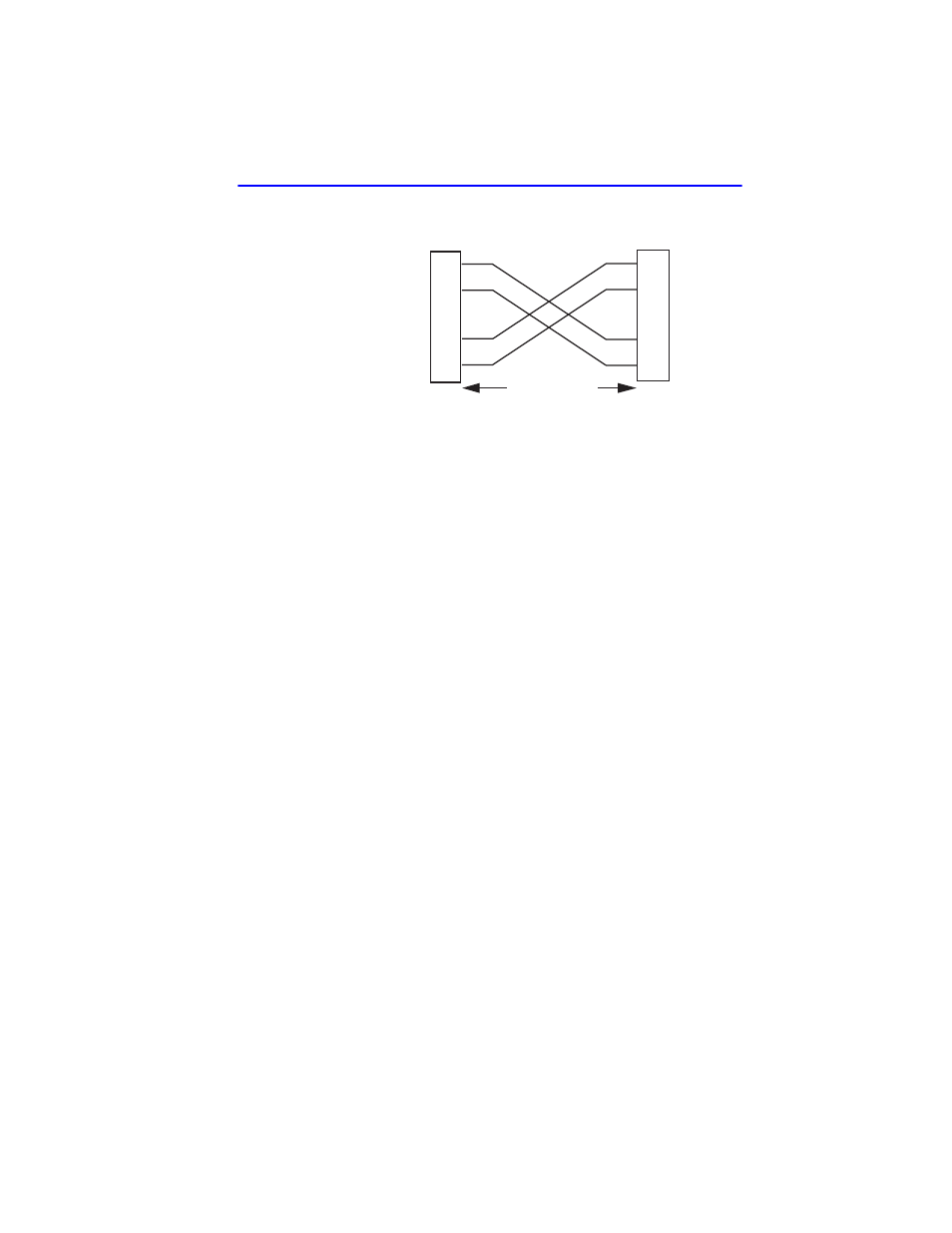
Figure 3-3
Cable Pinouts - (RJ45) Crossover Cable
c.
Ensure that the Twisted Pair connection meets the dB loss and
cable specifications outlined in Cabletron Systems Cabling Guide.
Refer to
, for information on
obtaining this document.
If a link is not established, contact the Cabletron Systems Global Call
Center. Refer to
4.
Repeat steps 1 through 3 above, until all connections have been made.
3.5.2
Connecting a Twisted Pair Segment to the
FE-100TX
An FE-100-TX installed in port 7 and/or 8 has an internal crossover
switch. When connecting a workstation, use a straight-through cable and
set the Fast Ethernet Interface Module crossover switch shown in
to the crossed over position marked with X. When connecting
networking devices, such as another bridge, repeater, or router, use a
straight-through cable and set the Fast Ethernet Interface Module
crossover switch shown in
to the not crossed over position,
marked with =.
A schematic of a crossover cable is shown in
. If the wires do
not cross over, use the switch on the FE-100TX to internally cross over
the RJ45 port.
shows how to properly set the FE-100TX
crossover switch.
TX+
TX–
RX+
RX–
2
1
3
6
TO
10BASE-T Device Port
TX+
TX–
2
1
3
6
NOTE:
RX+/RX– and TX+/TX–
must share a common
color pair.
TO
SmartSwitch RJ45 Port
2159_04
RJ45 to RJ45
RX+
RX–