Cabletron Systems Expansion module 6H122-08 User Manual
Page 164
Appendix C: Optional Installations and Mode Switch Bank Settings
C-6
6H122-08 User’s Guide
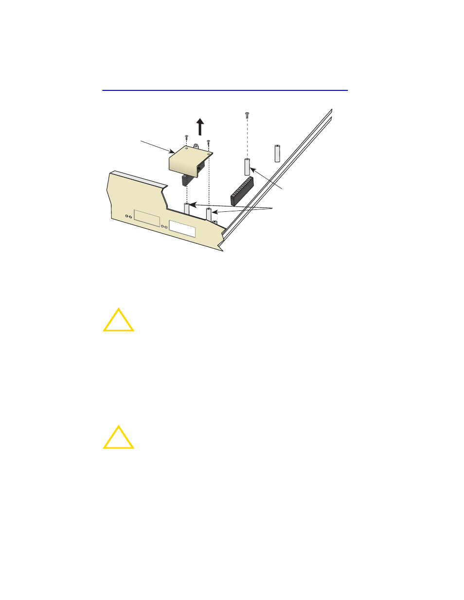
Figure C-3
Coverplate Removal
2.
Remove the screw from the rear standoff. Save the screw.
3.
. Gently pull the faceplate of the 6H122-08 forward to
allow room for the Fast Ethernet Interface Modules to be aligned over
the connector.
4.
Carefully lower the Fast Ethernet Interface Module onto the standoffs
while inserting the module connector into the associated motherboard
connector.
!
CAUTION
When installing an FE-100FX or FE-100F3 module into the
6H122-08, remove the rubber plug on the module before
proceeding.
!
CAUTION
When inserting the Fast Ethernet Interface Module into the
motherboard connector ensure that the pins do not bend, as
this can damage both the Fast Ethernet Interface Module and
the motherboard connector.
Front
Standoffs
Rear
Standoff
Coverplate
7
8
2159-32
- 2E42-27R (164 pages)
- 6H122-16 (158 pages)
- 24 (35 pages)
- 9T427-16 (16 pages)
- bridges (132 pages)
- CSX200 (88 pages)
- 2208 (158 pages)
- SM-CSI1076 (69 pages)
- SEHI-22 (93 pages)
- 9T425-16 (40 pages)
- 6000 (180 pages)
- 1800 (448 pages)
- ESX-1380 (86 pages)
- DLE23-MA (202 pages)
- 2E43-51 (168 pages)
- 5000 (83 pages)
- 6H253-13 (62 pages)
- Lancast Media Converter 7000 (108 pages)
- SmartCell 6A000 (102 pages)
- 9G421-02 (12 pages)
- SEH-22 (56 pages)
- 9A000 (180 pages)
- SEH-24 (64 pages)
- 6E123-26 (184 pages)
- STS16-20R (258 pages)
- 2E43-27 (164 pages)
- Cabletron MicroLAN 9E132-15 (36 pages)
- 9F120-08 (28 pages)
- 9E428-36 (18 pages)
- Device Management Module Dec GigaSwitch (65 pages)
- ELS10-26TX (18 pages)
- MICROMMAC-22T (105 pages)
- CSX1200 (644 pages)
- 7H02-06 (36 pages)
- 150 (106 pages)
- 9F206-02 (10 pages)
- MMAC-Plus 9T122-24 (27 pages)
- SEH100TX-22 (52 pages)
- 7C03 MMAC (16 pages)
- 2H253-25R (64 pages)
- TRXI-42 (92 pages)
- 7C04 (150 pages)
- 2H22 (120 pages)
- 2000 (196 pages)
- 7C04 Workgroup (25 pages)