Carrier 39L User Manual
Page 79
Occupied Cooling (31) — Indicates that the unit is in the
Cooling mode to satisfy its Occupied Cooling set point.
Occupied Fan Only (32) — Indicates that the unit is main-
taining set point by using a mixture of outside and return air
only. No mechanical heating or cooling is being used.
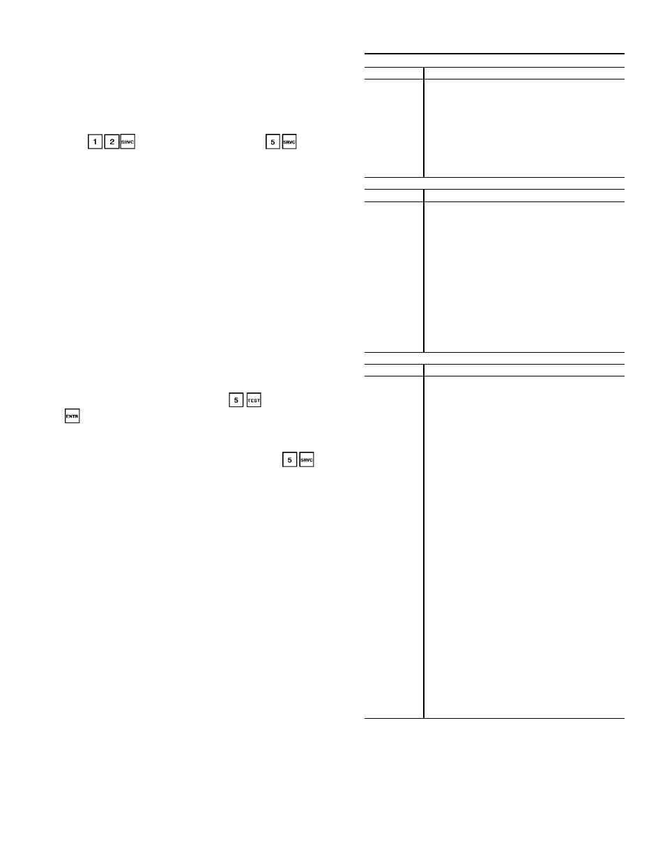
Nighttime Free Cooling (33) — Indicates that the supply fan
is on and using outside air to precool the space served by the
unit. Unit must be configured for nighttime free cool-
ing (
). (This mode is enabled by
.)
Smoke Pressurization (34) — Indicates that the unit is in the
Pressurization mode. This mode is issued from the fire
system panel. Refer to Table 15 for the state of the items
controlled.
Smoke Evacuation (35) — Indicates that the unit is in the
Smoke Evacuation mode. This mode is issued from the
system panel. Refer to Table 15 for the state of the items
controlled.
Smoke Purge (36) — Indicates that the unit is in the Smoke
Purge mode. This mode is issued from the fire system panel.
Refer to Table 15 for the state of the items controlled.
Fire Shutdown (37) — Indicates that the unit is in the Fire
Shutdown mode. This mode is issued from the fire system
panel or local smoke detector. Refer to Table 15 for the state
of the items controlled.
Quick Test (38) — Indicates that the unit is in the Quick Test
mode. It allows the user to test all inputs and outputs con-
nected to the PIC controller. All control routines are deac-
tivated when the unit is in this mode. This mode can only be
initiated manually when the supply fan status is OFF. (HOA
switch is in OFF position.) In order to reactivate all
the configured control routines, press
and then press
.
Timed Override (39) — Indicates that the unit operation has
been extended by the user. Unit must be configured for
Timed Override schedule and timed override hours (
).
Table 14 — Display Codes
FORCE STATES
Display
Description
1
Fire mode force
2
Internal safety force
3
Quick Test/Service tool force
4
HSIO/Building Supervisor force
5
Remote Building Supervisor force
6
Loadshed minimum offtime force
7
Data transfer force
8
BEST (Building Environmental Systems
Translator) force
9
Temperature override force
10
Loadshed force
OPERATING MODES
Display
Description
21
Temperature Reset in effect
22
Demand Limit in effect
23
Unoccupied Heating mode
24
Unoccupied Cooling mode
26
Optimal Start mode
27
Unoccupied mode
29
Optimal Stop mode
30
Occupied Heating mode
31
Occupied Cooling mode
32
Occupied Fan Only mode
33
Nighttime Free Cooling mode
34
Pressurization mode
35
Evacuation mode
36
Smoke Purge mode
37
Fire Shutdown mode
38
Quick Test mode
39
Timed Override mode
ALARMS
Display
Description
60
Air quality 1 high limit
61
Air quality 2 high limit
62
Air quality/constant outside air suspended
63
(Not used)
64
DX cooling shutdown
65
Pressurization
66
Evacuation
67
Smoke purge
68
Fire shutdown
69
Service/maintenance required
70
Linkage failure
71
Space temperature low limit
72
Space temperature high limit
73
Supply-air temperature low limit
74
Supply-air temperature high limit
75
Return-air temperature low limit
76
Return-air temperature high limit
77
Mixed-air temperature low limit
78
Mixed-air temperature high limit
79
Outside-air temperature low limit
80
Outside-air temperature high limit
81
Static pressure low limit
82
Static pressure high limit
83
Relative humidity low limit
84
Relative humidity high limit
85
Fan status
86
Freezestat
87
Analog temperature control sensor low limit
88
Analog temperature control sensor high limit
89
Outside-air relative humidity low limit
90
Outside-air relative humidity high limit
91
Supply velocity pressure low limit
92
Supply velocity pressure high limit
93
Return velocity pressure low limit
94
Return velocity pressure high limit
95
Delta CCFM low limit
96
Delta CCFM high limit
97
Filter status
98
Duct high humidity
CCFM — Cfm x 100
79