All 1, In. through 3-in. valve assemblies (see fig. 82) – Carrier 39L User Manual
Page 110
To remove the actuator from the high-temperature valve
linkage extension or from the 2-way normally-open valve
mounting nut, proceed as follows:
1. Secure the high-temperature linkage extension or
1
5
⁄
8
-in. valve mounting nut to prevent turning.
2. Turn the actuator base (by hand) counterclockwise off the
high-temperature linkage extension mating threads or off
the mating threads of the valve mounting nut. Do not ex-
ert force on the upper housing! If necessary, a 1
5
⁄
8
-in. open-
end wrench may be applied on the flats provided on the
actuator base.
3. Separate hydraulic actuator from linkage extension or valve
mounting nut. On assemblies using the linkage exten-
sion, retain the white spacer (now loose inside the ac-
tuator base) for reassembly later.
To reassemble the hydraulic actuator to the valve body:
1. On valve assemblies equipped with high-temperature link-
age extension, insert the white spacer inside the actuator
base.
2. Secure the high-temperature linkage extension or valve
mounting nut to prevent turning.
3. Turn the actuator base (by hand) clockwise onto the high-
temperature linkage extension or valve mounting nut un-
til secure. Do not exert force on the upper housing!
If necessary, a 1
5
⁄
8
-in. open-end wrench may be applied
on the flats provided on the actuator base. The actuator
may
be
rotated
as
desired
to
facilitate
wiring
connections.
All 1
1
⁄
2
-in. Through 3-in. Valve Assemblies
(See Fig. 82) —
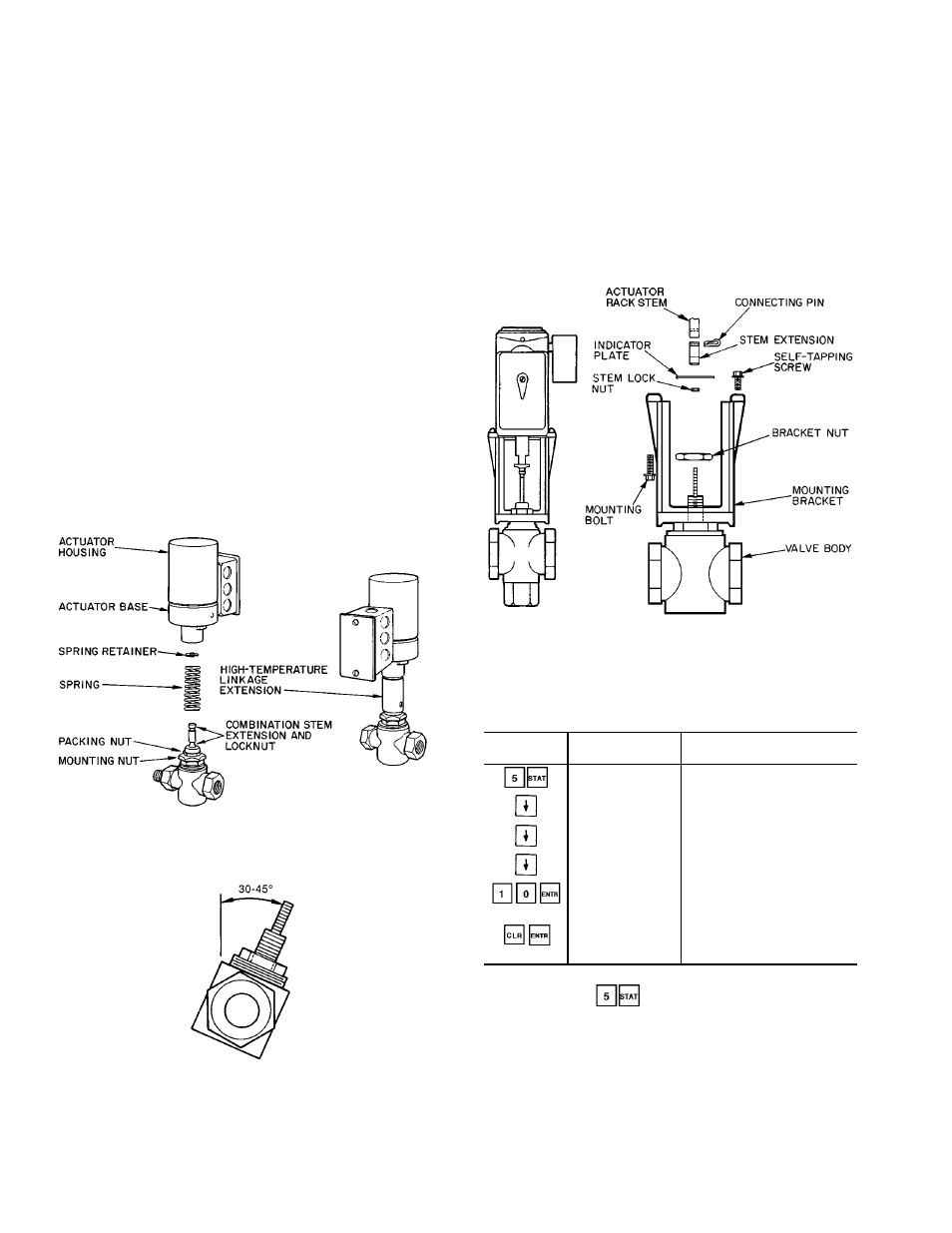
To remove the electro-mechanical ac-
tuator from the valve body, proceed as follows:
1. Electrically power the actuator by turning circuit breaker
to ON. Using the local interface device, force an output
of 10% (see Example 25), or enough to begin to move
the valve stem down, releasing stem pressure. It may be
necessary to slightly adjust the signal value up and down
to create a rocking motion on the valve stem. This will
permit easier connecting pin removal.
2. Remove the 2 self-tapping screws that secure the actua-
tor base to the linkage mounting bracket. Turn the power
to OFF and remove actuator assembly.
Example 25 — Forcing An Output
KEYBOARD
ENTRY
DISPLAY
RESPONSE
COMMENTS
OUTPUTS
System outputs
IGV %
Scroll past Inlet Guide Vane
status
MIXD %
Scroll past Mixed-Air Damper
status
HCV %
Heating Coil Valve status
HCV 10/FORCED
Heating Coil Valve is forced
10% (Display flashes
continuously)
HCV %
10% force is removed from
heating coil valve (Display
stops flashing)
NOTE: Electric heat and DX cooling stages cannot be forced. All
other outputs under
can be forced.
Fig. 80 — Valve Assemblies,
1
⁄
2
-in. to 1
1
⁄
4
-in.,
Typical Linkages
Fig. 81 — Valve Mounting Angle
Fig. 82 — Valve Assemblies, 1
1
⁄
2
-in. to 3-in.,
Typical Linkages
110