Legend (fig. 5-12, table 2) – Carrier 39L User Manual
Page 7
LEGEND (Fig. 5-12, Table 2)
AFS
— Airflow Switch
AO
— Analog Output
AOTC
— Analog Output Temperature Control
AQ
1
— Air Quality Sensor, No. 1
AQ
2
— Air Quality Sensor, No. 2
C
— Contactor
CCW
— Counterclockwise
CH
— Channel
CR
— Control Relay
CUST
— Condensing Unit Status
CV
— Constant Volume
CW
— Clockwise
CWV
— Chilled Water Valve
DHH
— Duct High Humidity
DO
— Discrete Output
DOTC
— Discrete Output Temperature Control
DSIO
— Control Module, Electric Heat and/or DX
DTCC
— Discrete Time Clock Control
DX
— Direct Expansion
DXS
— DX Cooling Stage
DXSD
— Direct Expansion Cooling Shutdown
EHS
— Electric Heaters
ELEC
— Electric
ENT
— Enthalpy Switch
EQUIP — Equipment
EVAC
— Smoke Evacuation Input
EXD
— Exhaust Air Damper Actuator
FLTS
— Filter Status Switch
FSD
— Fire Shutdown Device
FU
— Fuse
GND
— Ground
HIR
— Heat Interlock Relay
HOA
— Hand-Off-Auto. Switch
HPS
— High-Pressure Switch
HSIO
— Keyboard and Display Module
HT
— Heat
HUM
— Humidifier
HWV
— Hot Water Valve
IGV
— Inlet Guide Vane Actuator
LTT
— Low Temperature Thermostat
MAD
— Mixed-Air Damper Actuator
MAT
— Mixed-Air Temperature
MPSIO — Master Processor Module
(Processor Module)
OAD
— Outdoor-Air Damper Actuator
OARH
— Outdoor-Air Relative Humidity
OAT
— Outdoor-Air Temperature
OAVP
— Outdoor-Air Velocity Pressure
OT
— Outside-Air Thermostat
PH
— Preheat
PL
— Plug Assembly
PRESS — Smoke Pressurization Input
PSIO
— Processor Module
PURG
— Smoke Purge Input
RAD
— Return-Air Damper Actuator
RAT
— Return-Air Temperature
RFAN
— Return Fan
RFR
— Return Fan Relay
RFVC
— Return Fan Volume Control
RH
— Relative Humidity
RVP
— Return Velocity Pressure
SAT
— Supply-Air Temperature
SF
— Fan Status Relay
SFAN
— Supply Fan
SFR
— Supply Fan Relay
SMK
— Smoke
SNB
— Snubber
SP
— Static Pressure Transducer
SPSIO
— Slave Processor Module
(Option Module)
SPT
— Space Temperature
SVP
— Supply Velocity Pressure
SW
— Switch
TB
— Terminal Block Terminal
TEMP
— Temperature
TRAN
— Transformer
VAV
— Variable Air Volume
W/
— With
WO/
— Without
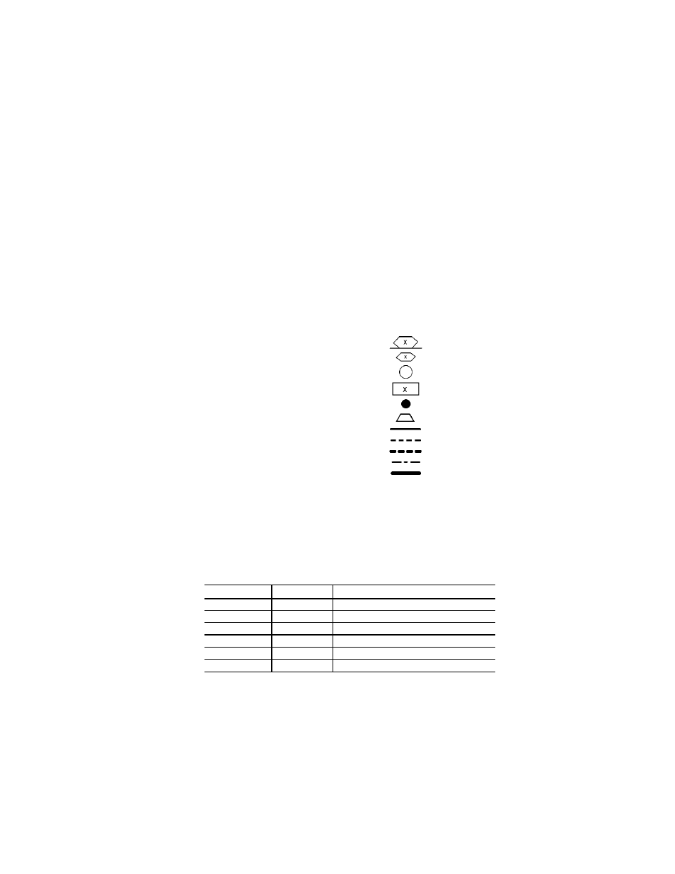
Marked Wire or Cable
Terminal (Marked)
Terminal (Unmarked)
Terminal Block
Splice (Factory)
Splice (Field)
Wiring Factory
Wiring Field Control
Wiring Field Power
Option or Accessory
Common Potential
NOTES:
1. Use copper conductors only.
2. Wire is in accordance with National Electrical Code (NEC). For local codes,
replace original wires with 90 C wire or its equivalent.
3. Replace wires from IGV, FLTS, MAT, SAT, OAD, RAD, and ELEC HT with
125 C plenum cable conductor as required.
4. Input channel numbers and points for configuration of the optional
analog output temperature control (AOTC) follow:
CHANNEL
SENSOR
DESCRIPTION
1
SAT
Supply-Air Temperature
2
OAT
Outdoor-Air Temperature
3
MAT
Mixed-Air Temperature
6
SPT
Space-Air Temperature
7
RAT
Return-Air Temperature
34
TEMP
Preheat or Optional Carrier Sensor
5. Reference for wire markers, where ‘X’ represents a numeral:
X
— Item number on wiring harness
BX — Box wire
CX — Cable
KX — Accessory kit wire
7