Unit troubleshooting (cont) – Carrier 39L User Manual
Page 114
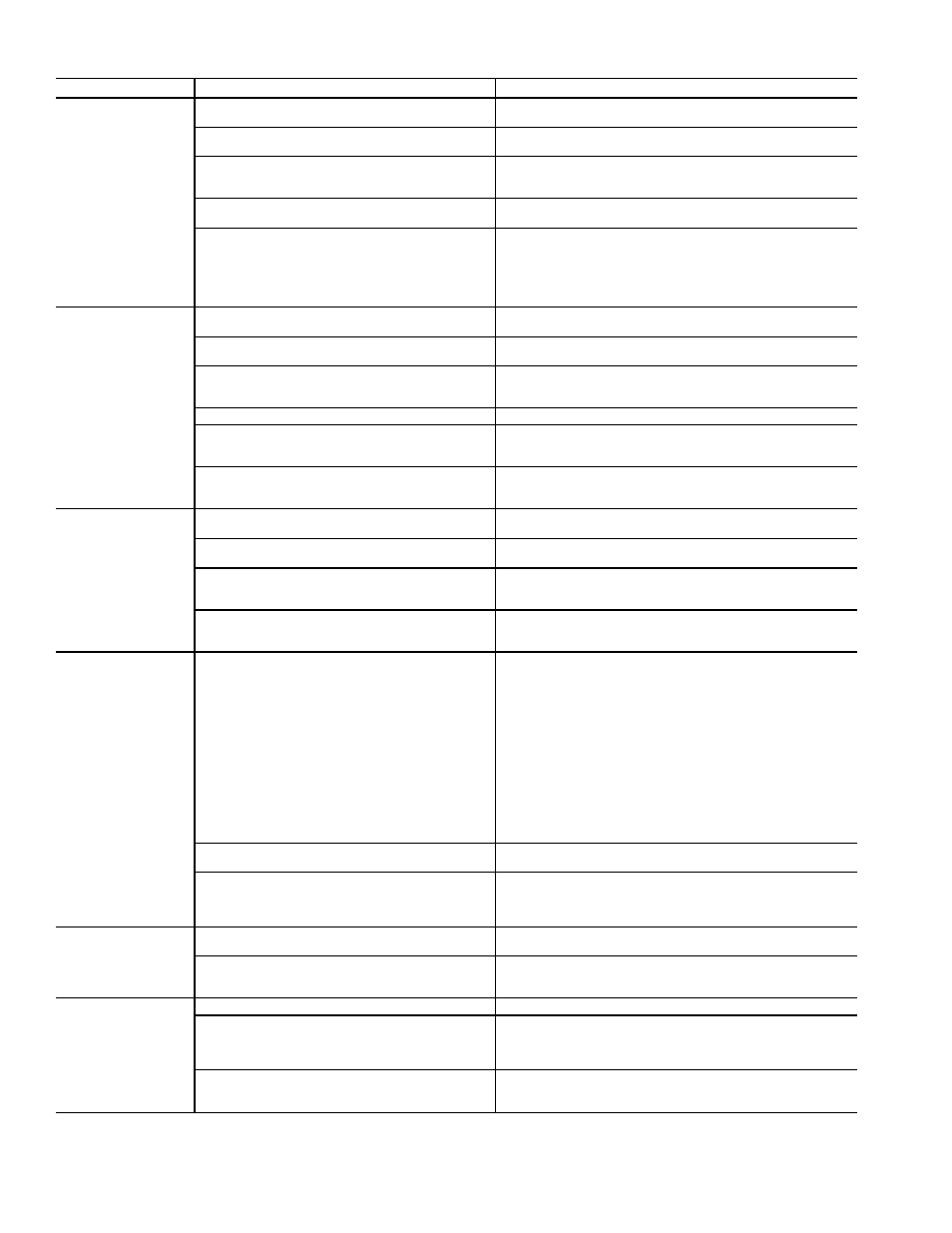
UNIT TROUBLESHOOTING (cont)
PROBLEM
POSSIBLE CAUSE
CORRECTIVE ACTION
Mixed-air dampers
will not operate
No fan status
Check status of SFS (4 STAT). If supply fan status switch is
OFF, check switch for proper operation.
Mixed-air dampers forced closed to outside air
Check status of MIXD (5 STAT). If MIXD is forced, remove
force and check operation.
No power to damper actuator
Check for blown fuse (F7). Replace if necessary. If fuse is
intact, check for proper connections. Check transformer
output.
Incorrect reading from space temperature sensor
or supply-air temperature sensor
Check status of sensor readings for accuracy. Replace sen-
sors if defective.
Configuration error
Check configuration for proper SMG and MDP (minimum
damper position). If MDP is set to zero, then dampers will
stay closed when enthalpy is unsuitable. An improper SMG
can cause the MIXD to be held to the MDP setting. Check
for proper damper set point. If damper set point is forced to
incorrect value, remove force.
Unit not main-
taining desired
static pressure
(VAV units only)
No fan status
Check status of SFS (4 STAT). If SFS is OFF, check supply
fan status switch for proper operation.
Inlet guide vanes (IGVs) forced closed
Check status of IGV (5 STAT). If IGVs are forced, remove
force and check operation.
No power to IGV actuator(s)
Check for blown fuse (F4). Replace if necessary. If fuse is
intact, check for proper connections. Check transformer for
proper output.
Loose IGV linkage
Check IGV linkage for tightness and proper adjustment.
Incorrect reading from static pressure transducer
Check status of sensor reading for accuracy. If reading is
in error, check for plugged sensing line and check sensor
calibration. Replace sensor if defective.
Configuration error
Check configuration for proper static pressure set point.
Also, check SMG. An improper SMG can cause the IGVs to
be held closed.
High-Pressure
Switch keeps
tripping unit
OFF (VAV only)
IGVs forced open
Check status of IGV (5 STAT). If IGVs are forced, remove
force and check operation.
High-Pressure Switch (HPS) is incorrectly set
or defective
Using squeeze bulb, check trip point of HPS. Adjust as re-
quired. Check for plugged lines. Replace if defective.
Static pressure sensor reads incorrectly
Using local interface device and squeeze bulb with gage,
verify static pressure reading is correct. Adjust or replace
sensor as required.
Configuration error
Check configuration for proper static pressure set point.
Check SMG. An improper SMG can cause the IGVs to be
held open.
Individual
actuators
do not function
No power, blown fuse
Check fuses of specific actuator for function failure.
Fuses are as follows:
F1 — PSIO control module
F2 — Power
F3 — Cooling coil
F4 — IGVs — supply fan
F5 — DSIO or option module
F6 — Heating coil
F7 — Mixed-air dampers
F8 — Smoke control or return-air damper
F9 — Exhaust-air damper
F10 — IGVs — return fan
F11 — 39NX sizes 74, 92; 2nd IGV actuator, supply fan
F12 — 39NX sizes 74, 92; 2nd IGV actuator, return fan
F13 — Preheat coil
Linkage is jammed or binding
Using manufacturer’s instructions, correct and adjust
linkage. Check operation.
No control signal
Using Quick Test and a voltage meter set to measure cur-
rent, verify that the proper control signal (4 to 20 mA) is be-
ing sent to the actuator. Refer to wiring diagram for
appropriate terminals.
Oscillating
output
(HCV, CCV, IGV,
MIXD, etc.)
Incorrect submaster gain
Using Control Loop Checkout procedure, page 108, adjust
the SMG until the output steadies.
Input sensor is fluctuating (supply-air
temperature sensor, static pressure transducer)
Verify sensor reading. If reading is fluctuating, determine
cause (i.e., loose connections, partially plugged static pres-
sure sensing lines). Correct or replace sensor if necessary.
Sensor
not reading
correctly
Loose connections
Verify all connections are secure.
Sensor out of calibration
Voltage type sensors (i.e., static pressure, space tempera-
ture, outdoor-air temperature, return-air temperature, rela-
tive humidity, and velocity pressure) can be calibrated using
manufacturer’s instructions.
Defective sensor
If a sensor cannot be calibrated and its reading is consid-
ered unacceptable, replace sensor. Once sensor is re-
placed, verify new sensor is reading correctly.
114