Carrier 39L User Manual
Page 112
If only the PSIO slave or DSIO module indicate commu-
nication failure, check the affected module for proper seat-
ing. If the condition persists even though connections are
correct, replace the module as described in the following
section.
Module Replacement (PSIO, DSIO) —
The PSIO
master module controls the standard unit functions, the PSIO
slave module controls many optional functions, and the DSIO
module controls electric heat and/or DX cooling. If the mod-
ule LEDs are not blinking and the unit or features associated
with the module do not work, the module may need to be
replaced. Before replacing an inoperative module, check to
ensure that:
• The PIC control box power is on
• Power at the processor module is between 18 and 24 vac
• No fuses are blown
• All connections are firmly in place
If all of the preceding conditions exist, and the module
LEDs are not blinking, the module needs to be replaced.
Before replacing a processor (PSIO) module, store the con-
figuration data from the old module on hard copy. The new
processor module can be preconfigured or configured in the
field.
After obtaining a new module, field-replace the inopera-
tive module as follows:
1. Turn off all power to the fan motor starter and PIC con-
trol box.
To avoid electrical shock and equipment damage,
always disconnect all power to the control box be-
fore replacing PIC modules.
2. Open the control box door.
3. Refer to Fig. 5-7 for control box component arrange-
ments. Disengage all connectors from the module.
4. Use a screwdriver to remove the mounting screw
securing the module to the control box. Remove the
module.
5. Install the replacement module and replace the mount-
ing screw.
6. Reinstall all connectors. Verify that each connector is in
the correct location.
7. Turn on the power to the PIC control box and motor
starter.
8. If you are replacing a PSIO master module that is not
preconfigured, use the local interface device (HSIO) or
Building Supervisor to reset the date and time and change
the module’s default settings. The original PSIO master
module was factory configured to match the unit in which
it was shipped. A replacement PSIO master mod-
ule must have the Factory Configuration (
) de-
faults changed in the field to match the configuration
of the unit in which it is being installed. Other settings
may also need to be reconfigured to match the unit con-
figuration and/or the original module’s settings.
9. Perform the Initial Check, run the Quick Test, and verify
that the unit is operating correctly as described in the
Start-Up section on page 103.
10. Close the PIC control box door.
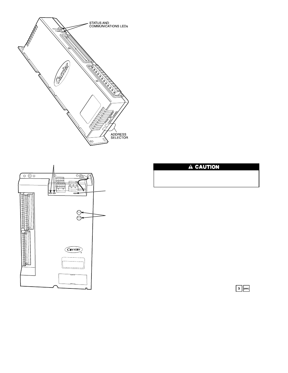
ADDRESS
SELECTOR
STATUS LED
COMMUNICATIONS
LEDs
Fig. 83 — Module Address Selector Switch
and LED Locations
DSIO
PSIO
112