Digital outputs from analog inputs, Figure 10-2 – Digilent 410-087P-KIT User Manual
Page 74
74
Spartan-3E Starter Kit Board User Guide
UG230 (v1.0) March 9, 2006
Chapter 10: Analog Capture Circuit
R
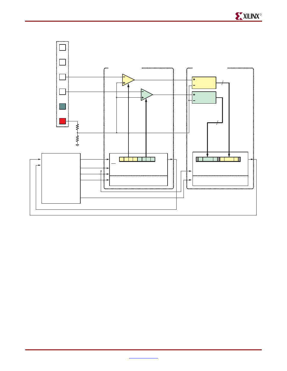
Digital Outputs from Analog Inputs
The analog capture circuit converts the analog voltage on VINA or VINB and converts it to
a 14-bit digital representation, D[13:0], as expressed by
Equation 10-1
The GAIN is the current setting loaded into the programmable pre-amplifier. The various
allowable settings for GAIN and allowable voltages applied to the VINA and VINB inputs
appear in
The reference voltage for the amplifier and the ADC is 1.65V, generated via a voltage
divider shown in
. Consequently, 1.65V is subtracted from the input voltage on
VINA or VINB.
The maximum range of the ADC is
±1.25V, centered around the reference voltage, 1.65V.
Hence, 1.25V appears in the denominator to scale the analog input accordingly.
Figure 10-2:
Detailed View of Analog Capture Circuit
Header J7
SPI_MOSI
AMP_CS
SPI_SCK
AMP_SHDN
AMP_DOUT
(N10)
(T4)
(U16)
(P7)
(N7)
Spartan-3E FPGA
LTC 6912-1 AMP
REFAB
REFCD
VINA
VINB
GND
VCC
(3.3V)
(3.3V)
(2.5V)
REF = 1.65V
A
B
CS/LD
DIN
SCK
SHDN
DOUT
SPI Control Interface
A GAIN
B GAIN
SCK
CONV
SDO
SPI Control Interface
CHANNEL 1
CHANNEL 0
AD_CONV
(P11)
SPI_MISO
(E18)
14
14
LTC 1407A-1 ADC
A/D
Channel 0
A/D
Channel 1
3
2
1
0
3
2
1
0
13
0
...
13
0
...
UG230_c10_02_022306
D 13:0
[
]
GAIN
V
IN
1.65V
–
(
)
1.25V
------------------------------------
Ч
8192
Ч
=