Ddr sdram, Chapter 13: ddr sdram, Chapter 13, “ddr sdram – Digilent 410-087P-KIT User Manual
Page 103: Chapter 13
Spartan-3E Starter Kit Board User Guide
103
UG230 (v1.0) March 9, 2006
R
Chapter 13
DDR SDRAM
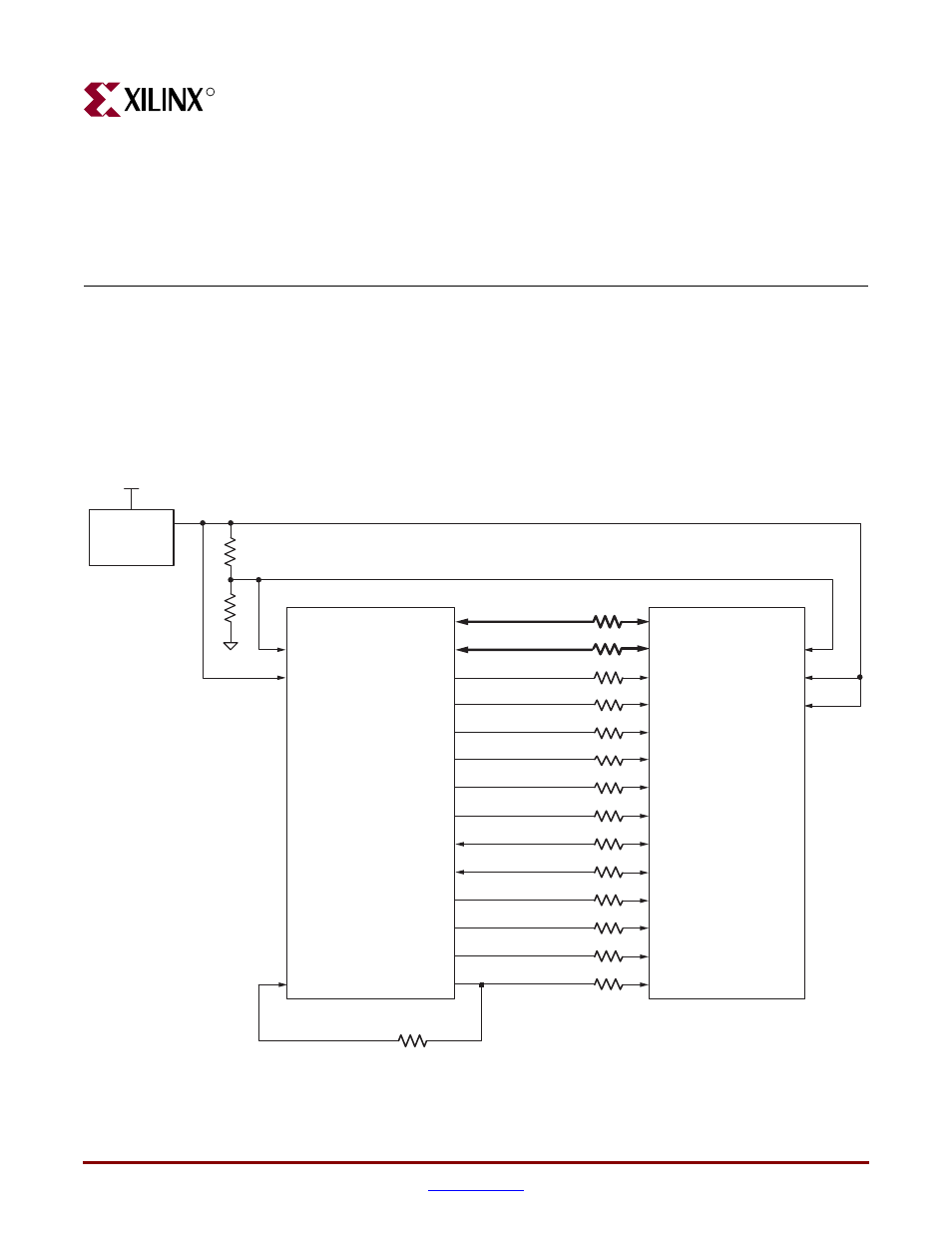
The Spartan-3E Starter Kit boards includes a 512 Mbit (32M x 16) Micron Technology DDR
SDRAM (MT46V32M16) with a 16-bit data interface, as shown in
. All DDR
SDRAM interface pins connect to the FPGA’s I/O Bank 3 on the FPGA. I/O Bank 3 and the
DDR SDRAM are both powered by 2.5V, generated by an LTC3412 regulator from the
board’s 5V supply input. The 1.25V reference voltage, common to the FPGA and DDR
SDRAM, is generated using a resistor voltage divider from the 2.5V rail.
All DDR SDRAM interface signals are terminated.
Figure 13-1:
FPGA Interface to Micron 512 Mbit DDR SDRAM
See Table
SD_A<12:0>
(C1)
Spartan-3E FPGA
SD_DQ<15:0>
SD_BA<1:0>
SD_RAS
A[12:0]
BA[1:0]
DQ[15:0]
RAS#
Micron 512 Mb DDR SDRAM
SD_CAS
SD_WE
SD_CK_P
SD_CK_N
SD_CKE
SD_CS
SD_LDM
SD_UDM
SD_UDQS
SD_LDQS
SD_CK_FB
CAS#
WE#
UQM
LQM
UDQS
LDQS
CS#
CK
CK#
CKE
See Table
See Table
(C2)
(D1)
(J1)
(J2)
(G3)
(L6)
(K4)
(K3)
(J4)
(J5)
(B9) GCLK9
VREF
VCCO_3
5.0V
LTC3412
VREF
VDD
VDDQ
2.5V
1.25V
MT46V32M16
(32Mx16)
UG230_c13_01_022406