Ucf location constraints, Rotary push-button switch, Locations and labels – Digilent 410-087P-KIT User Manual
Page 17: Operation, Locations and labels operation, Push-button switch, Figure 2-5, Figure 2-4
Spartan-3E Starter Kit Board User Guide
17
UG230 (v1.0) March 9, 2006
Rotary Push-Button Switch
R
In some applications, the BTN_SOUTH push-button switch is also a soft reset that
selectively resets functions within the FPGA.
UCF Location Constraints
provides the UCF constraints for the four push-button switches, including the
I/O pin assignment and the I/O standard used, and defines a pull-down resistor on each
input.
Rotary Push-Button Switch
Locations and Labels
The rotary push-button switch is located in the center of the four individual push-button
switches, as shown in
. The switch produces three outputs. The two shaft
encoder outputs are ROT_A and ROT_B. The center push-button switch is ROT_CENTER.
Operation
The rotary push-button switch integrates two different functions. The switch shaft rotates
and outputs values whenever the shaft turns. The shaft can also be pressed, acting as a
push-button switch.
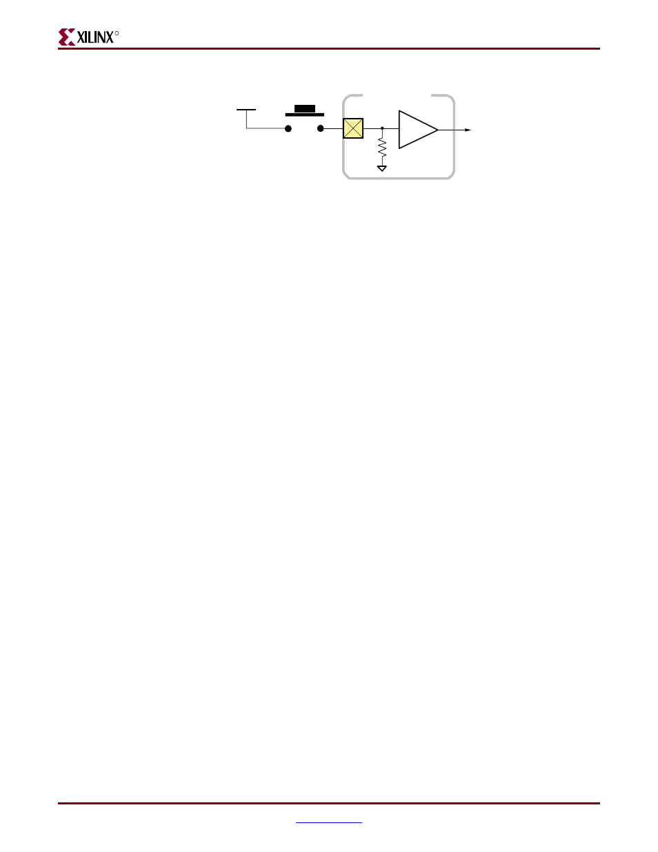
Push-Button Switch
Pressing the knob on the rotary/push-button switch connects the associated FPGA pin to
3.3V, as shown in
. Use an internal pull-down resistor within the FPGA pin to
shows how to specify a pull-down resistor within the UCF.
There is no active debouncing circuitry on the push button.
Figure 2-4:
Push-Button Switches Require an Internal Pull-Down Resistor in FPGA
Input Pin
UG230_c2_03_021206
BTN_* Signal
Push Button
3.3V
FPGA I/O Pin
Figure 2-5:
UCF Constraints for Push-Button Switches
NET
"BTN_EAST"
LOC
= "H13" |
IOSTANDARD
= LVTTL |
PULLDOWN
;
NET
"BTN_NORTH"
LOC
= "V4" |
IOSTANDARD
= LVTTL |
PULLDOWN
;
NET
"BTN_SOUTH"
LOC
= "K17" |
IOSTANDARD
= LVTTL |
PULLDOWN
;
NET
"BTN_WEST"
LOC
= "D18" |
IOSTANDARD
= LVTTL |
PULLDOWN
;