Switches, buttons, and knob, Slide switches, Locations and labels – Digilent 410-087P-KIT User Manual
Page 15: Operation, Ucf location constraints, Chapter 2: switches, buttons, and knob, Chapter 2, “switches, buttons, and knob, Chapter 2
Spartan-3E Starter Kit Board User Guide
15
UG230 (v1.0) March 9, 2006
R
Chapter 2
Switches, Buttons, and Knob
Slide Switches
Locations and Labels
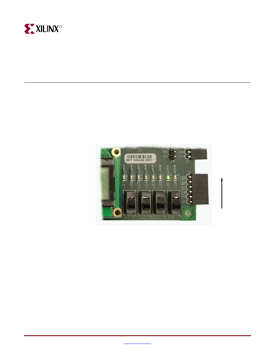
The Spartan-3E Starter Kit board has four slide switches, as shown in
. The slide
switches are located in the lower right corner of the board and are labeled SW3 through
SW0. Switch SW3 is the left-most switch, and SW0 is the right-most switch.
Operation
When in the UP or ON position, a switch connects the FPGA pin to 3.3V, a logic High.
When DOWN or in the OFF position, the switch connects the FPGA pin to ground, a logic
Low. The switches typically exhibit about 2 ms of mechanical bounce and there is no active
debouncing circuitry, although such circuitry could easily be added to the FPGA design
programmed on the board.
UCF Location Constraints
provides the UCF constraints for the four slide switches, including the I/O pin
assignment and the I/O standard used. The PULLUP resistor is not required, but it defines
the input value when the switch is in the middle of a transition.
Figure 2-1:
Four Slide Switches
UG230_c2_01_021206
LOW
HIGH
SW3
(N17)
SW2
(H18)
SW1
(L14)
SW0
(L13)