Keyboard – Digilent 410-087P-KIT User Manual
Page 62
62
Spartan-3E Starter Kit Board User Guide
UG230 (v1.0) March 9, 2006
Chapter 8: PS/2 Mouse/Keyboard Port
R
organized differently for a mouse and keyboard. Furthermore, the keyboard interface
allows bidirectional data transfers so the host device can illuminate state LEDs on the
keyboard.
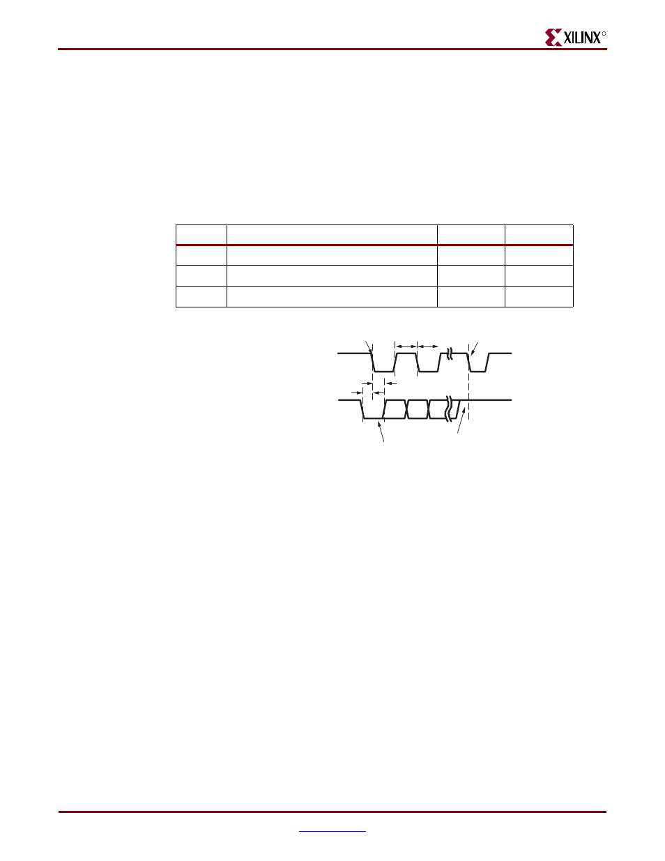
The PS/2 bus timing appears in
and
. The clock and data signals are
only driven when data transfers occur; otherwise they are held in the idle state at logic
High. The timing defines signal requirements for mouse-to-host communications and
bidirectional keyboard communications. As shown in
, the attached keyboard or
mouse writes a bit on the data line when the clock signal is High, and the host reads the
data line when the clock signal is Low.
Keyboard
The keyboard uses open-collector drivers so that either the keyboard or the host can drive
the two-wire bus. If the host never sends data to the keyboard, then the host can use simple
input pins.
A PS/2-style keyboard uses scan codes to communicate key press data. Nearly all
keyboards in use today are PS/2 style. Each key has a single, unique scan code that is sent
whenever the corresponding key is pressed. The scan codes for most keys appear in
If the key is pressed and held, the keyboard repeatedly sends the scan code every 100 ms or
so. When a key is released, the keyboard sends an “F0” key-up code, followed by the scan
code of the released key. The keyboard sends the same scan code, regardless if a key has
different shift and non-shift characters and regardless whether the Shift key is pressed or
not. The host determines which character is intended.
Some keys, called extended keys, send an “E0” ahead of the scan code and furthermore,
they might send more than one scan code. When an extended key is released, an “E0 F0”
key-up code is sent, followed by the scan code.
Table 8-2:
PS/2 Bus Timing
Symbol
Parameter
Min
Max
T
CK
Clock High or Low Time
30
μs 50
μs
T
SU
Data-to-clock Setup Time
5
μs 25
μs
T
HLD
Clock-to-data Hold Time
5
μs 25
μs
Figure 8-2:
PS/2 Bus Timing Waveforms
T
CK
T
SU
T
HLD
T
CK
Edge 0
Edge 10
CLK (PS2C)
DATA (PS2D)
'0' start bit
'1' stop bit
UG230_c8_02_021806