Rotary shaft encoder, Figure 2-6 – Digilent 410-087P-KIT User Manual
Page 18
18
Spartan-3E Starter Kit Board User Guide
UG230 (v1.0) March 9, 2006
Chapter 2: Switches, Buttons, and Knob
R
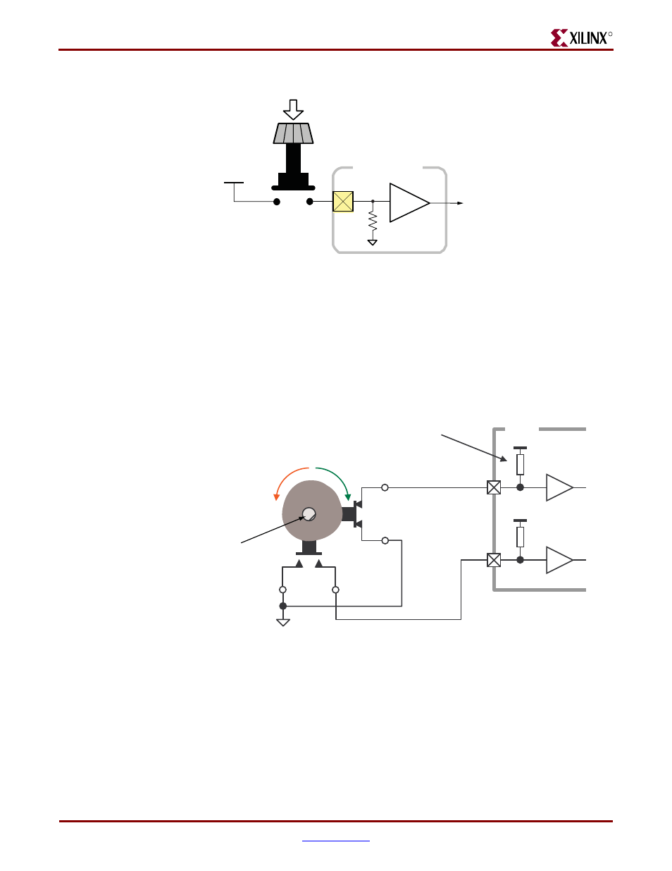
Rotary Shaft Encoder
In principal, the rotary shaft encoder behaves much like a cam, connected to central shaft.
Rotating the shaft then operates two push-button switches, as shown in
.
Depending on which way the shaft is rotated, one of the switches opens before the other.
Likewise, as the rotation continues, one switch closes before the other. However, when the
shaft is stationary, also called the detent position, both switches are closed.
Closing a switch connects it to ground, generating a logic Low. When the switch is open, a
pull-up resistor within the FPGA pin pulls the signal to a logic High. The UCF constraints
in
describe how to define the pull-up resistor.
The FPGA circuitry to decode the ‘A’ and ‘B’ inputs is simple, but must consider the
mechanical switching noise on the inputs, also called chatter. As shown in
, the
chatter can falsely indicate extra rotation events or even indicate rotations in the opposite
Figure 2-6:
Push-Button Switches Require Internal Pull-up Resistor in FPGA Input
Pin
UG230_c2_05_021206
Rotary / Push Button
ROT_CENTER Signal
3.3V
FPGA I/O Pin
Figure 2-7:
Basic example of rotary shaft encoder circuitry
GND
Vcco
Vcco
A=‘0’
B=‘1’
A pull-up resistor in each input pin
generates a ‘1’ for an open switch.
See the UCF file for details on
specifying the pull-up resistor.
FPGA
UG230_c2_06_030606
Rotary Shaft
Encoder