Installation and wiring – Toshiba Programmable Controller PROSEC T3 User Manual
Page 75
Attention! The text in this document has been recognized automatically. To view the original document, you can use the "Original mode".
4. Installation and Wiring
4.7
I/O wiring
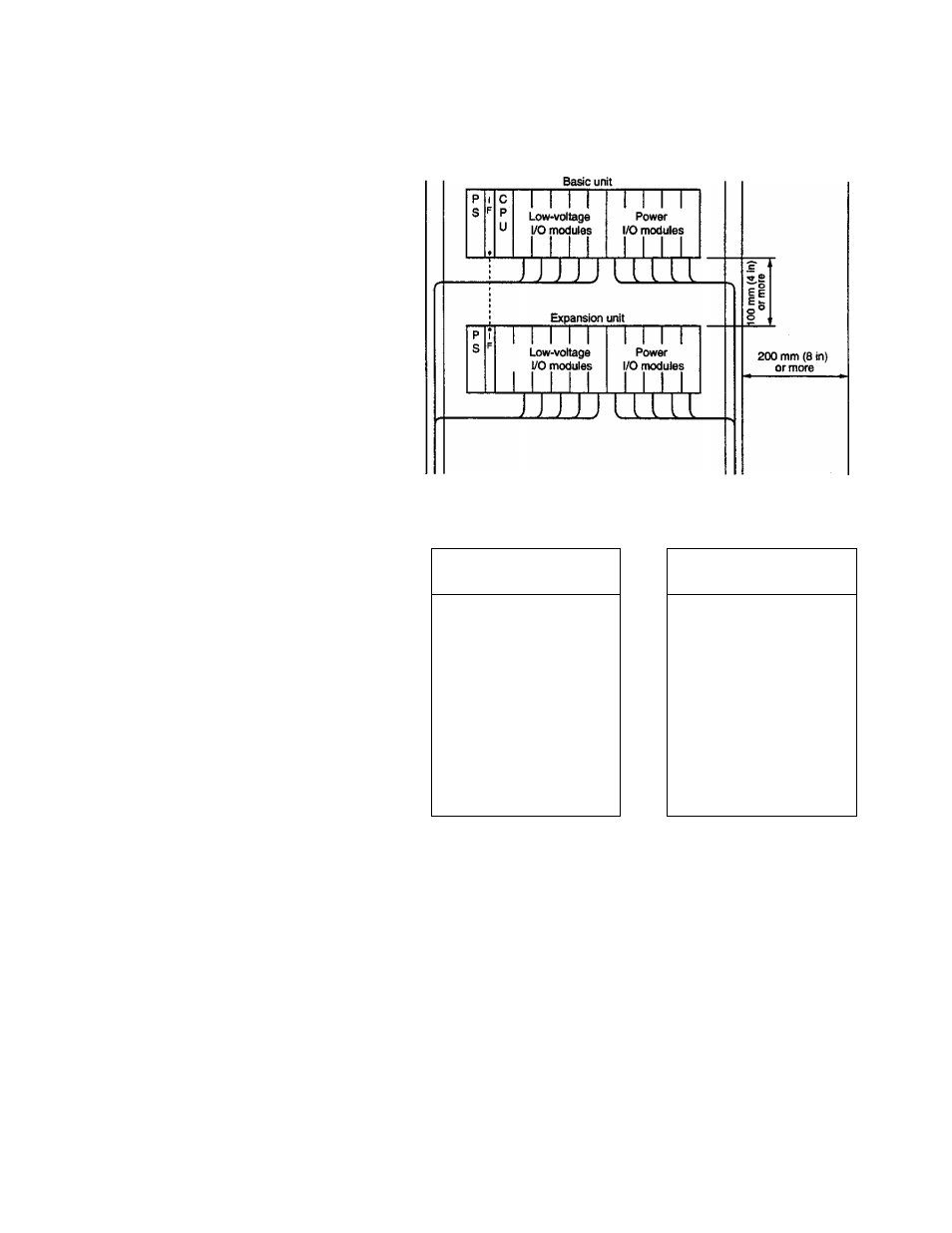
The following module layout is recommended for noise immunity.
Duct for
low-voltage
signals
Duct for
power signals
Power
caUes
I/O modules for
low-voltage system
I/O modules for
power system
DC input module
AC input module
Analog input module
DC output module
Analog ou^ut module
AC output module
Pulse input module
Relay output module
ASCII module
Data link module
(1) To improve the unit's resistance to signal interference, install
modules for low-voltage signals toward the left of the unit, and
modules for power signals toward the right. Also, separate the
wires of each,
(2> Allow at least
too
mm (4 in) clearance between the units and
between other control equipment to allow access for
maintenance and ventilation,
(3) When installing the unit near high-voltage or high-power
equipment, leave at least 200 mm (8 in) clearance, or shield the
unit with a steel plate.
User's manual - Hardware
67