Precautions for i/o modules – Toshiba Programmable Controller PROSEC T3 User Manual
Page 57
Attention! The text in this document has been recognized automatically. To view the original document, you can use the "Original mode".
3. Precautions for I/O Modules
R<
(V-Vd) Vo
V(Vd-Vo)
P= (2.5~3)
yL
R
2
V: Input voltage
Vo: Max. OFF voltage of the input module
Z i: Input impedance of the input module
In case of DI334,
V=24 Vdc, Vo=3-5 Vdc, Zi=2.4
kCl
If Vd=5 Vdc, R can be calculated as follows.
(24-5) X3.5
R[kQ]<_l----------
1
------ X2.4IkQ]
24X(5-3.5)
As a result,
R<4.4[kQ]->3kQ
{2AW
P=(2.5~3)X
3000[Q]
0.5W
Also, when the bleeder resistor is selected in the above manner,
the contact current at the switch ON state should be checked.
Contact current=24[V]X
2.4IkQ]+R
^18[mA]
2.4[kQ]XR
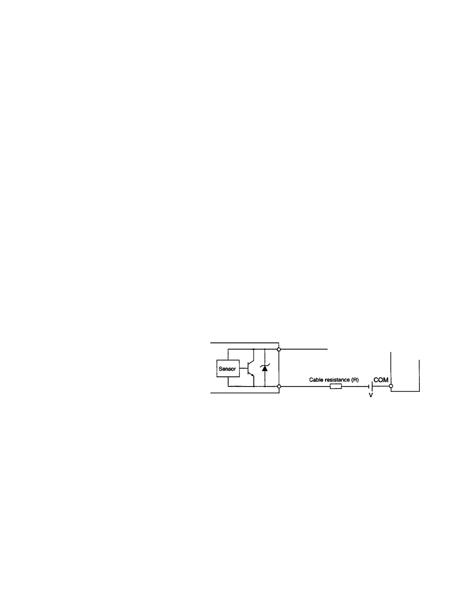
(4) If the two-wire proximity switch and other solid-state switches
are used, be sure that there is no possibility of mis-inputting
because of the leakage current, as in procedure (3). (See (3) for
details on how to select a bleeder resistor.)
Also in this case, because of the effect of the saturation voltage
(voltage drop) at ON, regardless of whether the switch is ON,
the input terminal voltage may not be able to reach the ON
voltage, thereby failing to read as input ON.
if input voltage is low or if input wiring is too long, special
measures are necessary.
Two-wire proximity switch
, ^ module
Cable resistance (R)
moouie
■ CD-------------6
if the cable resistance value is expressed as R[Q], Vd[V] for the
voltage drop of the proximity switch, and Zi[Q] for the input
impedance of the input module, the voltage Vi[V] applied
between the input module terminals will be as expressed below
(when the proximity switch is ON):
Vi=
V-Vd
2R+Zi
Zi
If the above Vi is lower than the minimum ON voltage of the
input module, input voltage V must be raised or the value of the
cable resistor R must be made smaller.
User's manual - Hardware
49