System configuration, 5 rack – Toshiba Programmable Controller PROSEC T3 User Manual
Page 27
Attention! The text in this document has been recognized automatically. To view the original document, you can use the "Original mode".
1. System Configuration
1.5
Rack
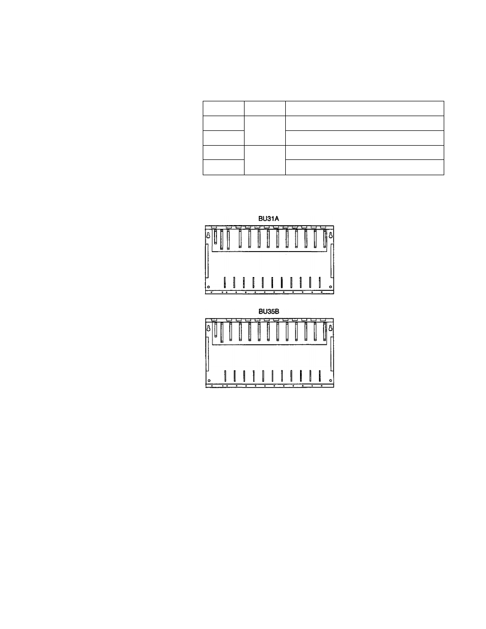
As described in the table below, in total four racks are available :
two racks are for the basic unit, and two racks, for the expansion
unit.
Type
Use
Number of modules mountable
BU31A
For
basic
unit
PSX1, IFX1, CPUX1,1/0X10
BU315
P S X I . I F X I . C P U X I , 1/0X5
BU35B
For
expansion
unit
P S X I . I F X I , 1/0X11
BU356
P S X 1 , I F X 1 , I / 0 X 6
) "PS" and "IF" in the above table indicate the power supply
module and the expansion interface module respectively.
BU315
I I I I I I
BU356
• The connector on the extreme-left slot of the rack is dedicated to
the power supply module, and the connector next to the right
slot is dedicated to the expansion interface module. The third
connector from the extreme left slot of the basic unit rack
(BU31A, BU315) is dedicated to the CPU module.
CAUTION Place a cap on each of the connectors where no module
is mounted so that no foreign material will enter.
User's manual - Hardware
19