Precautions for i/o modules – Toshiba Programmable Controller PROSEC T3 User Manual
Page 58
Attention! The text in this document has been recognized automatically. To view the original document, you can use the "Original mode".
3. Precautions for I/O Modules
(5) Because the input filter time constant of the high-speed
response input module (DI334H, D1335H) is set to small, the
input module may read the wrong input due to chattering of the
contact. Use the high-speed response input module to connect
with solid-state devices. Also, take measures to suppress noise.
(6) If input wiring is too long, take measures to prevent erroneous
input caused by noise, as follows.
•Wiring length must be minimized. Do not make unnecessary
loops.
•Keep the input wires away, at least 200 mm, from power
cables and high frequency lines, or shield the input cables
with a metal plate.
•If possible, use relays at the leading in the control panel.
•For some cases, use a shielded cable or twisted-pair cable.
•Install a bleeder resistor to reduce input impedance.
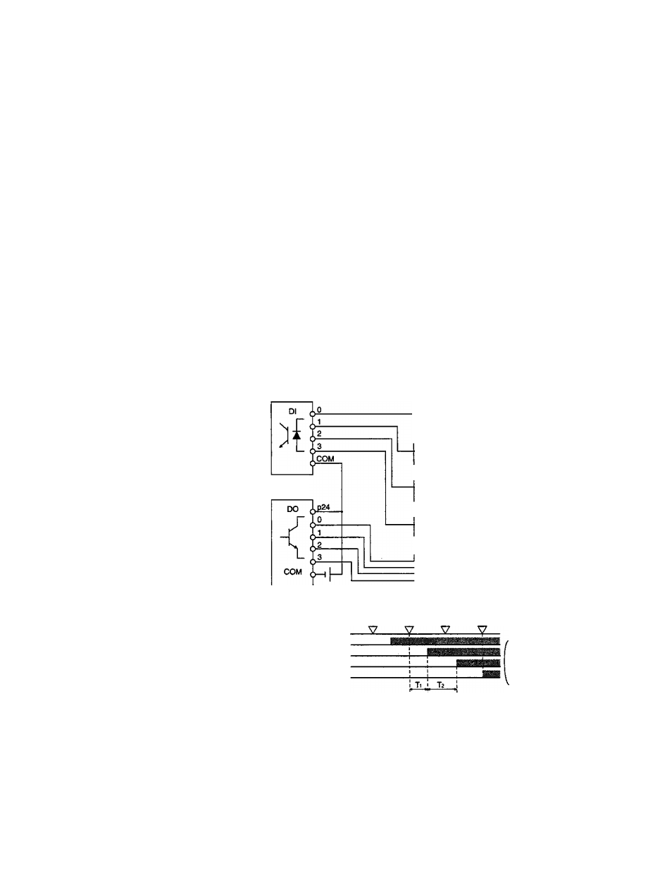
(7) If dynamic scan input is configured using a DC input module and
a DC output module, in addition to the response-delay of output
and input, consider the difference of timing caused by the PLC
scan. Moreover, diodes must be installed to prevent erroneous
input caused by detour circuit, (the figure below is an example of
4X4 input)
Input module
67a oTe 6jj 6|n
:
k
Output module
:
k
^
^
"6| n
K
For example, when contact a is ON, the change timing between
output 0 and input 0 is as follows :
PLC scan cycle
-Output 0
^internal)
Output
0 (external)
Input
0 (external)
Input
0
(internal)
T1 : Output response
delay
T2: Input response
delay
Note that the change timing of output 0 and input 0 will be
affected with the scan time of the PLC and the response time of
input and output.
50
PROSEC T3