Installation and wiring – Toshiba Programmable Controller PROSEC T3 User Manual
Page 67
Attention! The text in this document has been recognized automatically. To view the original document, you can use the "Original mode".
4. Installation and Wiring
4.3
Mounting modules
The power supply module must be mounted in the slot at the
extreme left of the rack. Install the expansion interface module in
the slot next to the power supply module, and the CPU module (for
the basic unit only) and I/O modules in the following slots :
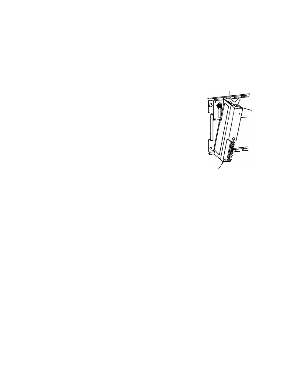
The modules, except for the expansion interface module, must be
installed as follows:
1. Slide back the slide lock
on the top of the module to
release the lock lever.
2. Hang the bottom of the
module on the rail of the
rack and push up the lock
lever.
3. While setting the bottom of
the module as the
supporting point, install the
module in the slot to match
the connector.
4. Release the lock lever and
lock the module in the rack.
Pull the slide lock towards
you and lock the lever.
Lock lever
Slide
lock
Screw
CAUTION •
TAT .
While operating, fix the module with a screw at the
bottom of the module.
Remove the module in the reverse procedure for
installation.
Connector covers are attached to the rack and
module connectors. Remove the connector
covers when a module is installed.
Mount an expansion interface module by using a screw in the slot
next to the power supply module slot as follows:
1. Insert the expansion interface module into the connector next
to the power supply module.
2. Tighten screws on top and bottom of the module.
CAUTION For safety, turn off power to the T3 before Installing or
removing a module. Also, refer to Section 6.8 I/O
module replacement during operation.
User's manual - Hardware
59