Precautions for i/o modules, I l l, 1 precautions for dc input modules – Toshiba Programmable Controller PROSEC T3 User Manual
Page 56
Attention! The text in this document has been recognized automatically. To view the original document, you can use the "Original mode".
3. Precautions for I/O Modules
3.1
Precautions for DC
Input modules
(1) Read conditions for the ON/OFFchanges of the input signals are:
Input ON time^ON delay time (OFF->ON)+lnput reading cycle
input OFF time^OFF delay time (ON->OFF)+lnput
reading cycle
Where the “input reading cycle“ means PLC scan cycle for the
refresh input, or the execution interval of a direct input instruction
when the instruction is used.
(2) For some external contacts, the input current (10 mA/24V for
DI334; 5 mA/24V for DI335) of modules may not be able to
maintain contact reliability. In this case, install a bleeder resistor
between the input and common terminals to increase the contact
current.
Contact
Input module
—---------0 O—'
—
\
t
II
y-
”
i l l
COM
V
wi
Wattage P> X(2.5~3)
R
(An example of selecting a bieeder resistor R)
Input voltage V=24 Vdc
Input module DI334 (10 mA/24 Vdc)
When the contact requires 50 mA current;
Resistance value R of a bleeder resistor=0.6[kQ]
Wattage P of the bleeder resistor=3[W]
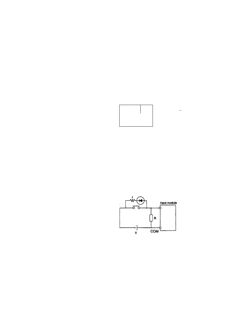
(3)
If a switch with an LED display is used, the current (leakage
current) through the LED may cause the erroneous input (always
ON). In this case, install a bleeder resistor to lower the input
impedance.
LED
(Example of selecting a bieeder resistor R)
When the voltage between input terminals is Vd at the switch
OFF state (with no bleeder resistor), the resistance (R) and the
wattage (P) of the bleeder resistor can be selected as follows.
48
PROSEC T3