System configuration – Toshiba Programmable Controller PROSEC T3 User Manual
Page 33
Attention! The text in this document has been recognized automatically. To view the original document, you can use the "Original mode".
1. System Configuration
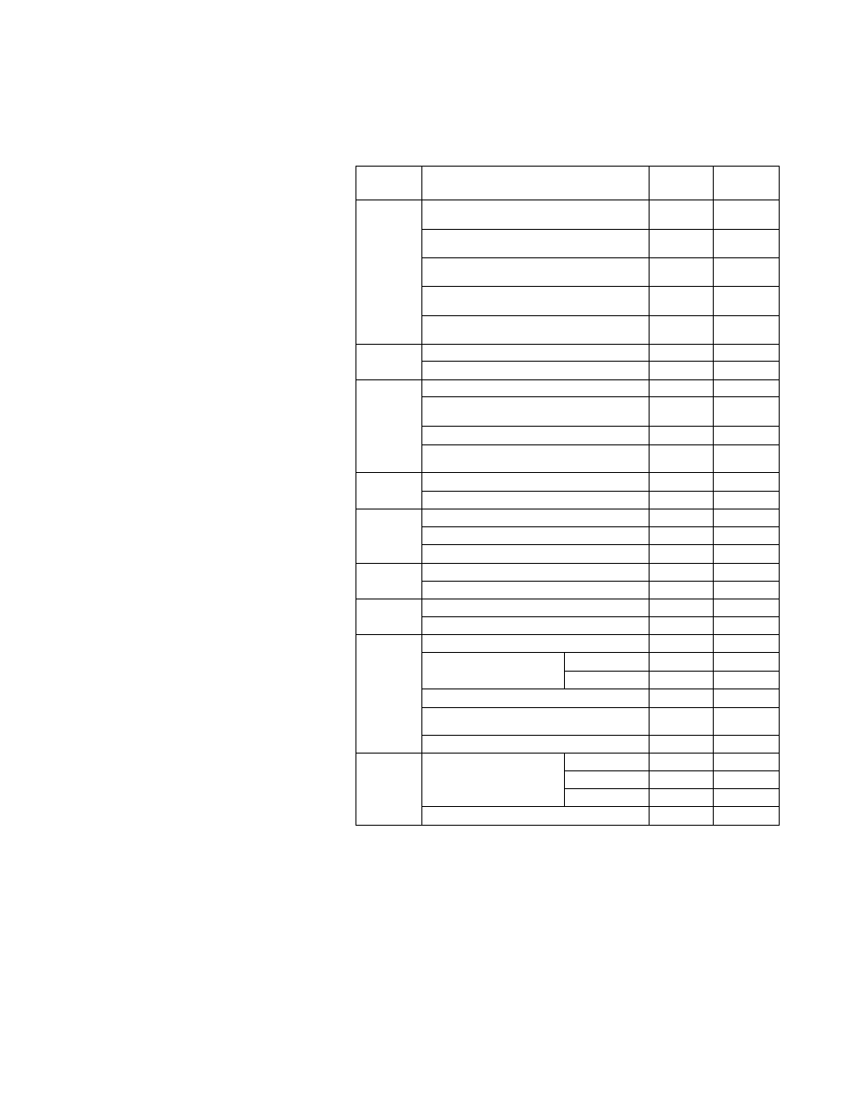
The table below lists the internal 5 Vdc current consumption (max.)
of the module for calculating allowable power capacity.
Type
Name
Part No.
Internal 5-
volt current
ccxisumption
Expansion
interface
Standard expansion interface
(for basic unit)
IF311
20 mA
Standard expansion interface
(for expansion unit)
IF351
20 mA
Long-distance expansion interface
(for basic unit)
IF312
800 mA
Long-distance expansion interface
(for middle expansion unit)
IF352
700 mA
Long-distance expansion interface
(for end expansion unit)
IF353
700 mA
CPU
CPU (RAM)
PU315
2.5 A
CPU (EEPROM+RAM)
PU325
2.5 A
DC
input
32-point DC input
DI334
100 mA
32-point DC input
(high-speed response)
DI334H
100 mA
64-point DC input
DI335
170 mA
64-point DC input
(high-speed response)
DI335H
170 mA
AC
input
32-point AC input (100 to 120 Vac)
IN354
120 mA
32-point AC input (200 to 240 Vac)
IN364
120 mA
DC
output
16-point DC ou^ut (12 to 24 Vdc)
D0333
320 mA
32-point DC output (12 to 24 Vdc)
D0334
210 mA
64-point DC output (5 to 24 Vdc)
D0335
400 mA
AC
output
16-point AC output (100 to 240 Vac)
AC363
530 mA
32-point AC ou^ut (100 to 240 Vac)
AC364
800 mA
Relay
output
32-point relay output
R0364
170 mA
10-point relay output (Isolated)
R0363S
100 mA
Special
I/O
Analog Input (8 channels)
AD368
460 mA
Analog output
(4 channels)
Voltage
DA364
180 mA
Current
DA374
180 mA
Pulse input (2 channels)
P1312
800 mA
DC input (8 pts) with status change
detection
CD332
300 mA
ASCII interface
AS311
1 A
Data link
TOSL1NE-S20
Coaxial
SN321
800 mA
Optic
SN322
800 mA
Coaxial/optic
SN323
800 mA
TOSLINE-F10 (master)
MS311
1 A
Note) The current consumption of the T3 CPU modules (2.5 A max.) is
the value when the handy programmer (HP911) is connected.
When the HP911 is not connected, it is 1.5 A max.
User's manual - Hardware
25