8 modbus software set-up, 1 bcm set-up for modbus operation, 2 monitoring and configuration only – AERCO Modulex E8 Controller (and BCM) For Modulex EXT Boilers User Manual
Page 88: E8 controller and bcm for modulex ext
E8 Controller and BCM for Modulex EXT
Installation, Operation & Maintenance Manual
CHAPTER 8: BOILER COMMUNICATION MODULE (BCM)
Page
88 of 108
AERCO International, Inc. • 100 Oritani Dr. • Blauvelt, NY 10913
OMM-0093_0A
PRI: 06/24/2013
Phone: 800-526-0288
GF-136-C
8.8 Modbus Software Set-Up
The following sections provide the information and procedures necessary to configure the Boiler
Communications Modules (BCMs) to operate on a Modbus Network.
8.8.1 BCM Set-Up For Modbus Operation
The BCM Controller can be set up for the following types of Modbus operating modes:
•
Monitoring and Configuration Only
•
AERCO BMS II/ACS Modbus Control and Monitoring
•
Modbus Remote Setpoint Control and Monitoring
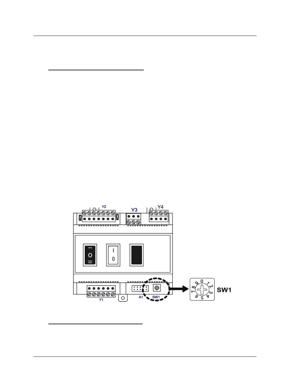
In order for the BCM Controller to be recognized by the Modbus Master, a valid address must
be set at each BCM on the Modbus Network. Address selection on each BCM is accomplished
by setting rotary DIP switch SW1. This switch is located in the lower right portion of each BCM
as shown in Figure 8-12.
SW1 is a 10-position switch labeled 0 – 9 (Figure 8-12). SW1 is set to the desired position using
a small flat-tip screwdriver. Figure 8-12 shows SW1 set to address 0 (zero) which disables the
BCM on the Modbus Network. Only Modbus addresses 1 through 9 will be recognized by the
Modbus Master. SW1 must be set to a different position for each Modulex Boiler being
controlled on the Modbus Network.
Once the desired address has been set on each BCM, the Modulex Boiler is configured for
Modbus Network control by the controlling Master EMS/BAS or AERCO BMS II/ACS. In order
for the BCM to act as the Back-Up Controller if the Modbus Master signal is lost, the
ENABLE/DISABLE switch must be set to ENABLE (1).
See Chapter 9 of this document and Chapter 2 of GF-124 for Modbus points for the BCM and
BMS II/ACS.
Figure 8-12: Location of BCM Address Selection Switch SW1
8.8.2 Monitoring and Configuration Only
For monitoring and configuration only, set the 3-position switch to position II when the E8 is
controlling the boiler. The boiler operation can be monitored via the Modbus terminals.