Chapter 3: e8 controller operation, 1 normal mode operation (door closed), 1 normal mode display functions – AERCO Modulex E8 Controller (and BCM) For Modulex EXT Boilers User Manual
Page 11
E8 Controller and BCM for Modulex EXT
Installation, Operation & Maintenance Manual
CHAPTER 3: E8 CONTROLLER OPERATION
OMM-0093_0A
AERCO International, Inc. • 100 Oritani Dr. • Blauvelt, NY 10913
Page
11 of 108
GF-136-C
Ph.: 800-526-0288
PRI: 06/24/2013
CHAPTER 3: E8 CONTROLLER OPERATION
The E8 Controller operates in NORMAL Mode when the controller door is closed, which allows
for monitoring the boiler status through the display window and setting the HEATING Mode.
When the door is opened, the unit enters MENU Mode, and in this mode the boiler may be
initialized, configured, and adjusted. The controls and display for the E8 controller are described
in the following sections.
3.1 NORMAL Mode Operation (Door Closed)
When the hinged door is closed on the E8, the unit is in NORMAL Mode.
3.1.1 NORMAL Mode Display Functions
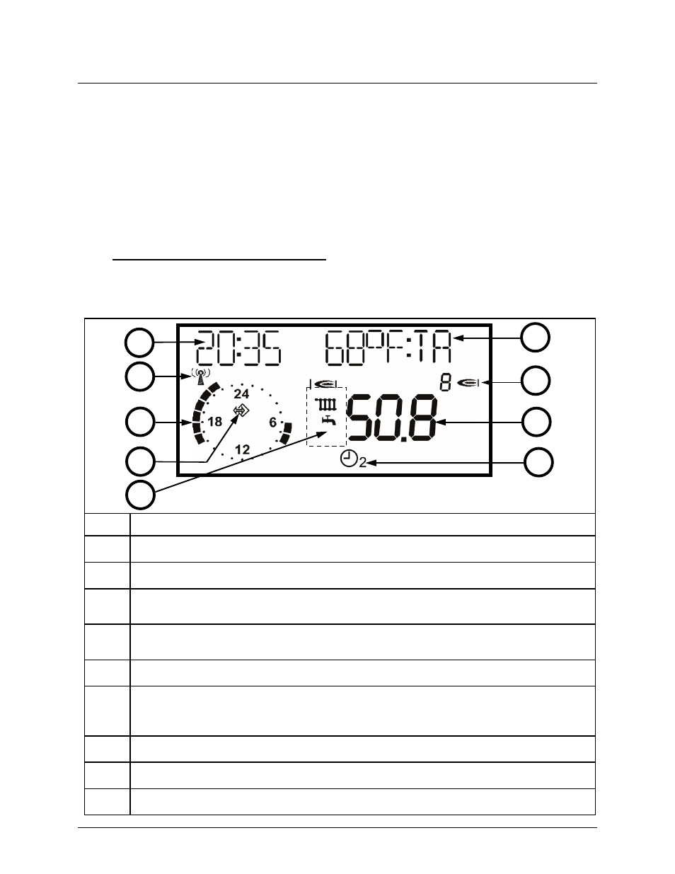
Figure 3-1 describes the types of information provided on the LCD display when in NORMAL
Mode (door closed). Note that the display in the illustration is only an example, and that an E8
Controller in service will show information appropriate for its configuration.
Figure 3-1: E8 Display (NORMAL Mode)
ITEM
FUNCTIONS
A
Current time (24 hour format)
B
DCF reception OK (only if receiver is connected via eBUS)
C
Display of the active heating program for the first heating circuit (here: 6:00 to 08:00
a.m. and 4:00 to 10:00 p.m.)
D
Bus icon (if this icon does not appear, check data line to connected CAN controllers
=> check eBUS via DISPLAY level)
E
Status display: Shows symbols for Internal Burner 1 Relay ON; Heating Mode; Hot Water Preparation.
F
Heating Mode display symbol. The display symbols apply to all internal heating
circuits for which a separate heating mode has been selected. Note that each
symbol occupies a different space across the display bottom. See Figure 3-2.
G
Display of current temperature of HS 1 or header temperature when cascading.
H
Display of number of active burners (only applies when cascading).
I
Selectable display and Error Codes ("DISPLAY SEL" parameter in USER menu).
A
B
C
D
E
I
H
G
F