7 modbus network wiring diagram, E8 controller and bcm for modulex ext, Installation, operation & maintenance manual – AERCO Modulex E8 Controller (and BCM) For Modulex EXT Boilers User Manual
Page 86: Caution, Chapter 8: boiler communication module (bcm)
E8 Controller and BCM for Modulex EXT
Installation, Operation & Maintenance Manual
CHAPTER 8: BOILER COMMUNICATION MODULE (BCM)
Page
86 of 108
AERCO International, Inc. • 100 Oritani Dr. • Blauvelt, NY 10913
OMM-0093_0A
PRI: 06/24/2013
Phone: 800-526-0288
GF-136-C
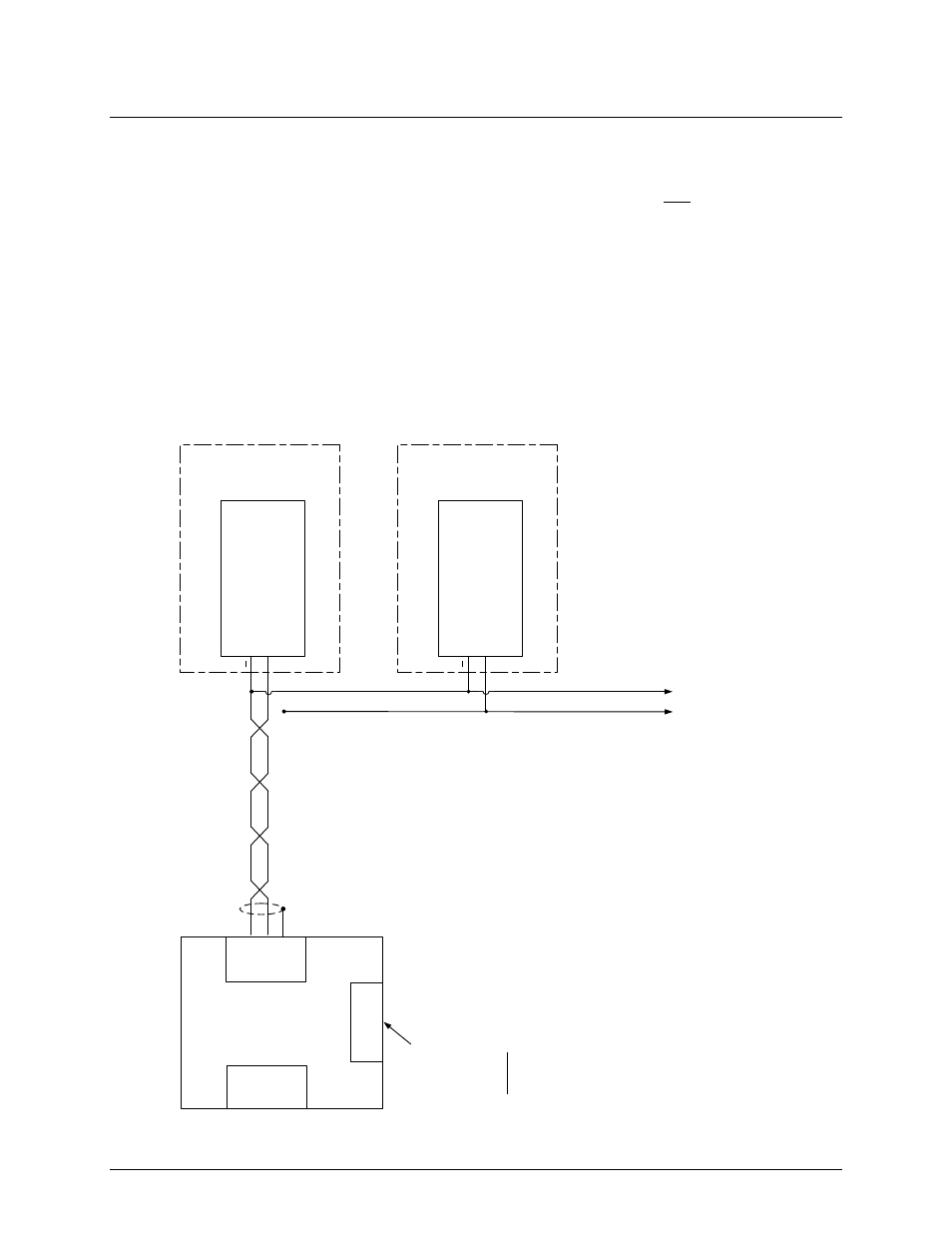
8.7 Modbus Network Wiring Diagram
A “Sample” Modbus Network wiring diagram for an AERCO BMS II/ACS Master controlling BCM
Slaves is shown in Figure 8-10. Activate the terminating resistor in the last BCM on the daisy-
chain loop. DO NOT install the 1K bias resistor. Instead, activate the two bias DIP switches in
the BMS II/ACS. Refer to GF-124 for the location of these switches.
CAUTION!
It is imperative that polarity be maintained between all Modbus
Network connections. The Network will not operate if the proper
polarity is not maintained. Also, twisted-pair wiring shields should
only be terminated at the controlling Master for the Modbus
Network.
TO OTHER NETWORK BOILER SLAVES
(3
- 9
)
AERCO BMS II
MASTER
485
B
+
485
A
-
RS485
PORT
SHLD
(TERM
3)
+
Y
2-
2
– MODBUS “A”
(-
)
(PART OF BCM CONN
. Y
2)
MODULEX BOILER SLAVE
#1
NOTES
:
THE LAST BCM SLAVE ON THE RS
485
LOOP
MUST HAVE ITS TERMINATION RESISTOR ENABLED
.
ALSO
,
THE
2
BIAS DIP SWITCHES IN THE BMS II
SHOULD BE TURNED ON
,
Y
2-
1
– MODBUS “B”
(+)
BCM
+
Y
2-
2
– MODBUS “A”
(-
)
(PART OF BCM CONN
. Y
2)
MODULEX BOILER SLAVE
#2
Y
2-
1
– MODBUS “B”
(+)
BCM
RS232
PORT
BIAS DIP
SWITCHES
(2
)
SET BOTH
SWITCHES TO “ON”
Figure
7-
10
.
AERCO BMS II Master Controlling Modulex Boiler Slaves
Figure 8-10: AERCO BMS II Master Controlling Modulex Boiler Slaves