2 bcm controller terminating resistor and bias, E8 controller and bcm for modulex ext – AERCO Modulex E8 Controller (and BCM) For Modulex EXT Boilers User Manual
Page 85
E8 Controller and BCM for Modulex EXT
Installation, Operation & Maintenance Manual
CHAPTER 8: BOILER COMMUNICATION MODULE (BCM)
OMM-0093_0A
AERCO International, Inc. • 100 Oritani Dr. • Blauvelt, NY 10913
Page
85 of 108
GF-136-C
Ph.: 800-526-0288
PRI: 06/24/2013
feet) can usually operate satisfactorily without the terminating resistor. However, longer loop
runs (over 1000 feet), may require terminating resistors.
Bias may be necessary on the RS485 loop to minimize noise on the circuit. Loop bias is
accomplished by activating pull-up/pull-down resistors on the last Boiler Communications
Module (BCM) in the chain. AERCO recommends that both terminating resistors and bias be
implemented on the RS485 circuit as described in Sections 8.6.1 and 8.6.2, which follow.
8.6.1 Master BMS II/ACS or EMS/BAS Terminating Resistor and Bias
All AERCO BMS II/ACS units are equipped with a built-in terminating resistor. Therefore, when
the BMS II or ACS is the controlling Master, no terminating resistor needs to be added. In
addition, the BMS II/ACS contains two Bias DIP switches which must be activated when the
BMS II/ACS is the controlling Master. Refer to BMS II Manual GF-124/ACS Manual GF-131,
Section 2.6 and Figure 2-6 for additional information on these switches.
When a third-party EMS or BAS is used as the controlling Master, consult the manufacturer’s
Technical Manual for termination resistor recommendations. If the EMS/BAS being used does
not provide a bias and one is needed, pull-down bias can be implemented by installing a 1K
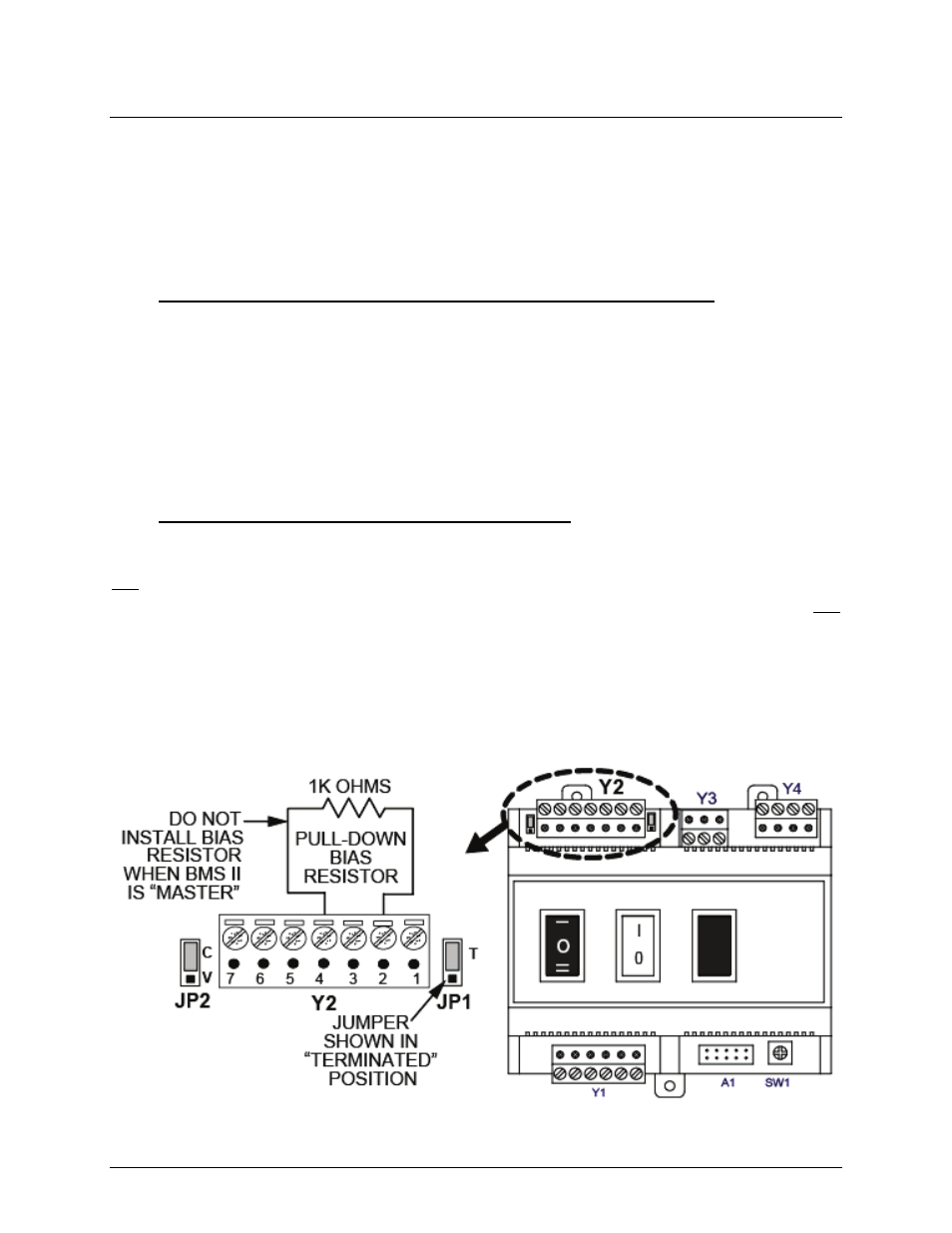
ohm resistor (not provided) across terminals 2 and 4 on BCM connector Y2 (Figure 8-9).
8.6.2 BCM Controller Terminating Resistor and Bias
BCMs can function only as Slave devices on a Modbus Network. Since the Slaves are
connected in a “Daisy-Chain” configuration, the terminating resistor must be enabled only in the
last BCM Controller in the chain. Enabling the terminating resistor is accomplished by
positioning jumper JP1 as shown in Figure 8-9 only on the BCM Board contained in the last
BCM Controller.
As mentioned in Section 8.6.1, when the controlling Master is an EMS or BAS, pull-down bias
may be implemented by connecting a 1K ohm resistor as shown in Figure 8-9. DO NOT install
this bias resistor if the controlling Master is an AERCO BMS II or ACS. Bias will be provided by
the BMS II/ACS DIP switches. The last unit in the chain must be energized (even if disabled) to
enable bias.
Figure 8-9: BCM Loop Termination and Bias