1 bcm fault relay wiring, 2 clearing faults, 3 bcm configured as back-up controller – AERCO Modulex E8 Controller (and BCM) For Modulex EXT Boilers User Manual
Page 80: 1 bcm back-up controller wiring, E8 controller and bcm for modulex ext
E8 Controller and BCM for Modulex EXT
Installation, Operation & Maintenance Manual
CHAPTER 8: BOILER COMMUNICATION MODULE (BCM)
Page
80 of 108
AERCO International, Inc. • 100 Oritani Dr. • Blauvelt, NY 10913
OMM-0093_0A
PRI: 06/24/2013
Phone: 800-526-0288
GF-136-C
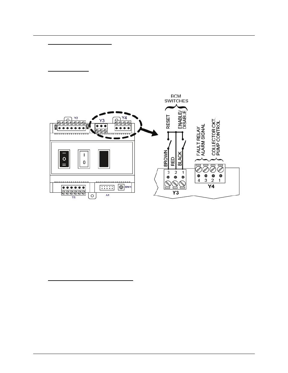
8.2.1 BCM Fault Relay Wiring
If desired, pins 3 and 4 of connector Y4 (Figure 8-3) can be wired to an external source to
provide a remote alarm indication when the BCM Fault Relay is activated.
8.2.2 Clearing Faults
A fault can be cleared by pressing and releasing the black Reset Switch on the front cover of
the BCM. However, if the cause of the fault has not been corrected, the Fault Relay will again
be activated.
Figure 8-3: BCM Fault Relay & Reset Switch Wiring
8.3 BCM Configured as Back-Up Controller
When the BCM is configured as the Back-Up Controller for the E8, it will assume control of the
Modulex Boiler if the E8 fails. In the event of an E8 Controller failure, the BCM will operate the
Modulex Boiler in the Constant Setpoint Mode (default setpoint = 180°F [82°C]). The primary
Boiler Pump must also be wired to the BCM so it will run when the BCM assumes control in the
Back-Up Mode.
If a setpoint temperature lower than 180°F is desired, the setpoint can be changed prior to boiler
start-up. Refer to Section 8.3.1 for details.
8.3.1 BCM Back-Up Controller Wiring
The Primary Boiler Pump must be wired to BCM Connector Y4 as shown in Figure 8-4. Also, if
a Constant Setpoint temperature lower than the default setting of 180°F (82°C) is desired in the
event of an E8 failure, the appropriate resistor must be connected across terminals 6 and 7 of
BCM Connector Y2 as shown in Figure 8-5.