Chapter 7: e8 connector terminal assignments, 1 sensor terminal assignments – AERCO Modulex E8 Controller (and BCM) For Modulex EXT Boilers User Manual
Page 73
E8 Controller and BCM for Modulex EXT
Installation, Operation & Maintenance Manual
CHAPTER 7: E8 CONNECTOR TERMINAL ASSIGNMENTS
OMM-0093_0A
AERCO International, Inc. • 100 Oritani Dr. • Blauvelt, NY 10913
Page
73 of 108
GF-136-C
Ph.: 800-526-0288
PRI: 06/24/2013
CHAPTER 7: E8 CONNECTOR TERMINAL ASSIGNMENTS
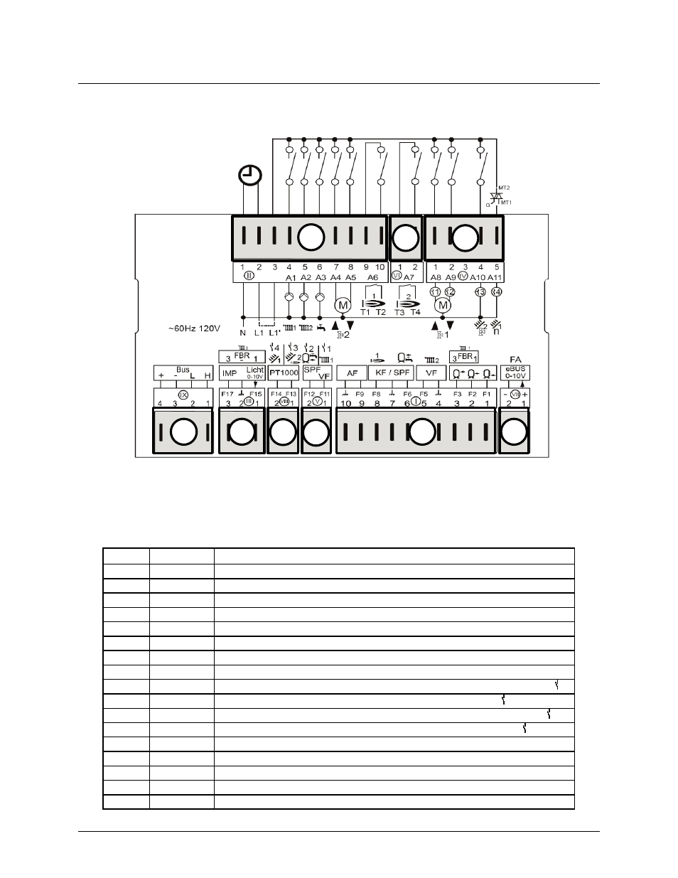
Figure 7-1: E8 Controller Rear Panel Terminals
7.1 SENSOR Terminal Assignments
Table 7-1: Sensor Terminal Assignments
Term
Pin#
Function
7
(1+2)
Ebus (FA) or 0-10V output
1
(1,2,3+M) F1/F2/F3 = buffer storage tank low/middle/top
1
(2+3+M) FBR2 (FBR1) for heating circuit 1
1
(2+M)
F2 = Room sensor for heating circuit 1
1
(4+5)
F5 = Flow sensor heating circuit 2
1
(6+7)
F6 = Storage tank sensor
1
(7+8)
F8 = Boiler sensor/header sensor
1
(9+10)
F9 = Outdoor sensor
5
(1+M)
F11 = Flow sensor heating circuit 1/Multifunction relay sensor 1
5
(2+M)
F12 = Hot-water tank low/Multifunction relay sensor 2
8
(1+M)
F13 = PT1000 => HS2/collector 2/Multifunction relay sensor 3
8
(2+M)
F14 = PT1000 => Collector 1/Multifunction relay sensor 4
3
(1-3)
FBR2 (FBR1) for heating circuit 2
3
(1+2)
F15 = 0-10V input/light sensor/Room sensor for heating circuit 2
3
(2+3)
F17 = Pulse counter for output measurement
9
(1+2)
Data line CAN bus
9
(3+4)
Power supply CAN bus
4
6
2
9
3
8 5
1
7
120V~; Relay switching
capacity 2(2)A, 250V~