5 bcm control of vfd primary pump, 1 pump control wiring, 2 pump control operation – AERCO Modulex E8 Controller (and BCM) For Modulex EXT Boilers User Manual
Page 84: 6 rs485 loop termination resistors and bias, E8 controller and bcm for modulex ext
E8 Controller and BCM for Modulex EXT
Installation, Operation & Maintenance Manual
CHAPTER 8: BOILER COMMUNICATION MODULE (BCM)
Page
84 of 108
AERCO International, Inc. • 100 Oritani Dr. • Blauvelt, NY 10913
OMM-0093_0A
PRI: 06/24/2013
Phone: 800-526-0288
GF-136-C
8.4.4 AERCO BMS II/ACS Master to BCM Slave Wiring Connections.
The AERCO BMS II/ACS contains a RS232 port for connection to an EMS/BAS or personal
computer. In addition, the BMS II/ACS contains a RS485 port for connection to the BCM’s
Modbus input.
8.4.5 EMS or BAS Master to BCM Slave Wiring Connections
When a third-party EMS or BAS Master is used, the Modbus Network connections will depend
on the available communication port(s) on the EMS/BAS. Many EMS/BAS Models contain only
a RS232 (DB9) port, while others contain either a 2-Wire or 4-Wire RS485 port. In addition,
some EMS/BAS models contain both a RS232 and a RS485 port. If the EMS or BAS is
equipped with only a RS232 port, a RS232-to-RS485 converter will be required (such as a B&B
Electronics, Model 485SD9TD or AERCO Part No. 124943).
8.5 BCM Control of VFD Primary Pump
The BCM has a 0-10 V output that can be used to control a VFD primary pump. There is no
connection on the Modulex controller for pump mains power. Pump mains power must be
supplied externally, as directed by pump manufacturer’s instructions.
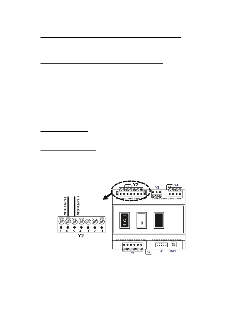
8.5.1 Pump Control Wiring
The 0-10 V signal wire must be wired to terminals 5 and 6 of terminal block Y2. See Figure 8-8.
The positive wire connects to terminal 5 and the negative to terminal 6.
8.5.2 Pump Control Operation
Adjustment of the 0-10 V signal is done through 3 Modbus registers. For setup and operation of
Modbus controls see Sections 8.7, 8.8, and 8.9. Data address 3006 is the “Pump Over-run
Time” and it controls the amount of time, in minutes, that the pump will continue to run after the
unit is shut down. Addresses 3007 and 3008 control the output voltage at minimum and
maximum fire, respectively. For further information see Table 9-4.
Figure 8-8: Primary Pump Control Wiring to BCM
8.6 RS485 Loop Termination Resistors and Bias
A terminating resistor (120 ohms) on each end of the RS485 loop is designed to match the
electrical impedance characteristic of the twisted-pair loop and prevent echoes or cross-talk
from corrupting data on the line. Short or medium length Modbus/RS485 loops (less than 1000